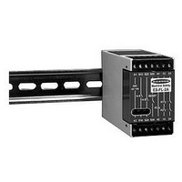
ES-FL-2A BANNER ENGINEERING, ES-FL-2A Datasheet - Page 7

ES-FL-2A
Manufacturer Part Number
ES-FL-2A
Description
20H6269
Manufacturer
BANNER ENGINEERING
Datasheet
1.ES-FL-2A.pdf
(8 pages)
Specifications of ES-FL-2A
Coil Voltage Vac Nom
24V
Coil Voltage Vdc Nom
24V
Contact Current Max
4A
Contact Voltage Ac Nom
250V
Contact Voltage Dc Nom
250V
Contact Configuration
DPDT-NC
No. Of Poles
2
3) Apply input power (only) to the ES-FL-2A safety relay at terminals A1 and A2. Verify that only the Input Power indicator (Figure
4) Arm the emergency stop switch (close its contacts). Close the reset switch. The K1 and K2 indicators should remain off. Open the
5) Activate the emergency stop switch (open its contacts). The K1 and K2 indicators should turn off, simultaneously. If either
6) Close the enclosure. Apply power to the machine control elements and perform the Periodic Checkout Procedure (see following
IMPORTANT NOTE: If more than one emergency stop switch is series-connected to one ES-FL-2A safety relay, the above checkout
procedure must be run individually for EACH switch.
We recommend that the emergency stop system be checked at each shift change or machine setup change.
1) With the machine running, engage the emergency stop switch (open its contacts). Verify that the machine stops.
2) Return the emergency stop switch to its closed-contact position. Close and then open the reset switch. Verify that the machine restarts.
IMPORTANT NOTE: If two or more emergency stop switches are series-connected to one ES-FL-2A safety relay, this test must be
individually run for EACH switch.
NOTE: Do not attempt any repairs to the ES-FL-2A Emergency Stop Monitoring Safety Relay. It contains no field-replaceable
components. Return the safety relay to the factory for warranty repair or replacement:
SECTION 6 – Periodic Checkout Procedure
SECTION 7 – Repairs
WARRANTY: Banner Engineering Corporation warrants it products to be free from defects for one year.
Banner Engineering Corporation will repair or replace, free of charge, any product of its manufacture found
to be defective at the time it is returned to the factory during the warranty period. This warranty does not
cover damage or liability for the improper application of Banner products. This warranty is in lieu of any
other warranty either expressed or implied.
1) is on. If either of the other two indicators is on at this point, disconnect the input power and check all wiring. Return to
step 2 after the cause of the problem has been corrected.
reset switch. The K1 and K2 indicators should both come on at this time. If either indicator comes on before the reset switch is
opened, disconnect the input power and check all wiring. Return to step 2 after the cause of the problem has been corrected.
indicator does not go off, disconnect the input power and check all wiring. Return to step 2 after the cause of the problem has
been corrected.
information).
Banner Engineering Corp.
715 North County Rd. 19
Aberdeen, SD 57401
Repair Department
E-Stop Safety Relay
page
7


