CW4K-32DE11N4 IDEC, CW4K-32DE11N4 Datasheet - Page 4
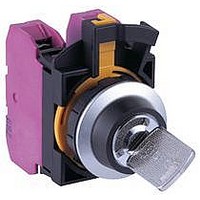
CW4K-32DE11N4
Manufacturer Part Number
CW4K-32DE11N4
Description
59T4365
Manufacturer
IDEC
Datasheet
1.CW1P-1EQ3R.pdf
(20 pages)
Specifications of CW4K-32DE11N4
Contact Configuration
1NO / 1NC
Switch Operation
Spring Return From Left
Angle Of Throw
45°
Actuator Style
Key
No. Of Switch Positions
3
Contact Current Max
10A


ø22mm Flush Mount CW Switches & Pilot Devices
4
4
• ø 22.3mm mounting hole compliant with IEC 60947-5-1
• 3 .5-mm operator travel for pushbuttons ensures comfortable and reliable
• B lack and metallic bezels available
• I lluminated pushbuttons, pushbuttons, pilot lights, selector switches and key
• D irect opening NC contact
• S even different keys can be chosen for key selector switches
• 1 0A contact rating; up to three contact blocks for non-illuminated and two
• C ontact blocks can be removed by the two-action locking lever integrated with
• I P20 finger-safe screw terminals
• I P65 degree of protection (IEC 60529) from panel front
Contact Ratings
1. Minimum applicable load (reference value): 3V AC/DC, 5 mA (Applicable range is subject to
2. The operational current represents the classification by making and breaking currents (IEC
3. UL, c-UL rating: A300
Weights
Flush bezel projects only 2.5mm from front of panel and
only 39.9mm behind the panel!
Applicable Standards
UL508
CSA C22.2 No.14
EN60947-5-1
Rated Insulation Voltage (Ui)
Rated Thermal Current (Ith)
Rated Operating Voltage (Ue)
Rated
Operating
Current
(Ie)
Contact Material
Illuminated Pushbutton
Pushbutton
Pilot Light
Selector Switch
Key Selector Switch
operation
selector switches are available
contact blocks for illuminated models can be connected
a guard, ensuring safety
the operating conditions and load.)
60947-5-1).
Electrical
Life
50,000
operations
Electrical
Life
100,000
operations
AC
50/60 Hz
DC
AC
50/60 Hz
DC
46g (CW1L-M1E02QH, 2 contact blocks)
45g (CW1B-M1E03, 3 contact blocks)
27g (CW1P-1EQH)
48g (CW1S-2E03, 3 contact blocks)
61g (CW1K-2E03, 3 contact blocks)
Mark
Resistive Load
(AC-12)
Inductive Load
(AC-15)
Resistive Load
(DC-12)
Inductive Load
(DC-13)
Resistive Load
(AC-12)
Inductive Load
(AC-15)
Resistive Load
(DC-12)
Inductive Load
(DC-13)
File No. or Organization
UL/c-UL File No. E68961
TÜV SÜD
EC Low Voltage Directive
10A
10A
24V
8A
4A
5A
5A
4A
2A
0.55A
Silver
300V
120V
2.2A
1.1A
1.1A
10A
10A
6A
5A
3A
0.55A
0.55A
0.27A
240V
1.1A
1.5A
6A
3A
3A
Specifications
Direct Opening of Key Selector Switch
Operating Temperature
Operating Humidity
Storage Temperature
Contact Resistance
Insulation Resistance
Overvoltage Category
Impulse Withstand
Voltage
Pollution Degree
Vibration Resistance
Shock Resistance
Mechanical Life
(minimum operations)
Electrical Life
(minimum operations)
Degree of Protection
(IEC60529)
Short-circuit Protection
Electrical Shock
Protection
Terminal Style
Bezel Material
Applicable Wire Size
Recommended
Tightening Torque
Operator Angle for Direct Opening Action
Minimum Operator Torque for Direct
Opening Action
Maximum Operator Angle
Non-illuminated: –25 to +60°C (no freezing)
LED illuminated: –25 to +55°C (no freezing)
45 to 85% RH (no condensation)
–40 to +80°C
50 mΩ maximum (initial value)
100 MΩ minimum (500V DC megger)
II (IEC 60664-1)
2.5 kV (IEC60664-1/60947-5-1)
3 (IEC60947-5-1)
Operating extremes: 5 to 55Hz, amplitude 0.5 mm
Operating extremes: 100 m/s
Damage limits: 1000 m/s
Pushbutton, illuminated pushbutton:
Selector switch:
Key selector switch:
50,000 (see Contact Ratings)
100,000 (see Contact Ratings)
(switching frequency 1800 operations/h)
Panel front:
Terminals:
250V/10A fuse, (Type aM IEC60269-1, IEC602069-2)
Class II (IEC61140)
Screw terminal (M3.5 slotted Phillips screw)
Polyamide
Up to 2 wires of 2 mm
maximum (AWG14 to 16) (Ring terminal cannot be
used)
Terminal:
Locking ring:
IP65
IP20
1.0 to 1.3 N·m
1.2 N·m
90°
0.2 N·m
90°
2-position (3NC) 3-position (2NC)
2
(solid wire ø1.6)
2
2
45°
0.3 N·m
45°
2,000,000
250,000
250,000
Related parts for CW4K-32DE11N4
Image
Part Number
Description
Manufacturer
Datasheet
Request
R

Part Number:
Description:
59T4362
Manufacturer:
IDEC
Datasheet:
Part Number:
Description:
59T4361
Manufacturer:
IDEC
Datasheet:
Part Number:
Description:
59T4364
Manufacturer:
IDEC
Datasheet:
Part Number:
Description:
59T4366
Manufacturer:
IDEC
Datasheet:
Part Number:
Description:
59T4363
Manufacturer:
IDEC
Datasheet:

Part Number:
Description:
Cable; Between IDEC MicroSmart (port 1 or 2) and HG2F/3F/4F; 5 ft.
Manufacturer:
IDEC Corporation
Datasheet:
Part Number:
Description:
Cable; Between IDEC Micro^3C/ONC/MicroSmart (port 2) PLCs and HG2F/3F/4F; 5 ft.
Manufacturer:
IDEC Corporation
Datasheet:
Part Number:
Description:
Angled Key for Idec HS6B Safety Switch
Manufacturer:
IDEC Corporation
Datasheet:
Part Number:
Description:
Accessory, L-Shaped Key for Idec HS5B and HS5E Safety Switch
Manufacturer:
IDEC Corporation
Datasheet:
Part Number:
Description:
Accessory, Straight Key for Idec HS5B and HS5E Safety Switch
Manufacturer:
IDEC Corporation
Datasheet:
Part Number:
Description:
INDICATOR INCANDESCENT LAMP, GREEN
Manufacturer:
IDEC
Datasheet:

Part Number:
Description:
LAMP, INDICATOR, INCAND, AMB
Manufacturer:
IDEC
Datasheet:
Part Number:
Description:
LAMP, INDICATOR, INCAND, GRN
Manufacturer:
IDEC
Datasheet:
Part Number:
Description:
LAMP, INDICATOR, INCAND, GRN
Manufacturer:
IDEC
Datasheet:
Part Number:
Description:
LAMP, INDICATOR, INCANDESCENT, RED
Manufacturer:
IDEC
Datasheet: