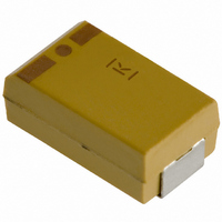
T494B107K010AT Kemet, T494B107K010AT Datasheet - Page 111

T494B107K010AT
Manufacturer Part Number
T494B107K010AT
Description
CAP TANT 100UF 10V 10% 1210
Manufacturer
Kemet
Series
T494r
Type
Moldedr
Datasheet
1.T494B107K010AT.pdf
(133 pages)
Specifications of T494B107K010AT
Capacitance
100µF
Voltage - Rated
10V
Tolerance
±10%
Esr (equivalent Series Resistance)
2.250 Ohm
Operating Temperature
-55°C ~ 125°C
Mounting Type
Surface Mount
Package / Case
1210 (3528 Metric)
Size / Dimension
0.138" L x 0.110" W (3.50mm x 2.80mm)
Height - Seated (max)
0.083" (2.10mm)
Lead Spacing
-
Manufacturer Size Code
B
Features
General Purpose
Lifetime @ Temp.
-
Lead Free Status / Rohs Status
Lead free / RoHS Compliant
Other names
399-5600-2
Tantalum Surface Mount Capacitors – Low ESR
KEMET Organic Capacitor (KO-CAP) – T530 High Capacitance/125°C Rated Polymer Tantalum
Soldering Process
KEMET’s families of surface mount capacitors are compatible
with wave (single or dual), convection, IR or vapor phase refl ow
techniques. Preheating of these components is recommended
to avoid extreme thermal stress. KEMET's recommended
profi le conditions for convection and IR refl ow refl ect the profi le
conditions of the IPC/J-STD-020D standard for moisture
sensitivity testing. The devices can safely withstand a maximum
of three refl ow passes at these conditions.
Note that although the X/7343-43 case size can withstand wave
soldering, the tall profi le (4.3 mm maximum) dictates care in wave
process development.
Hand soldering should be performed with care due to the diffi culty
in process control. If performed, care should be taken to avoid
contact of the soldering iron to the molded case. The iron should
be used to heat the solder pad, applying solder between the pad
and the termination, until refl ow occurs. Once refl ow occurs, the
iron should be removed immediately. "Wiping" the edges of a chip
and heating the top surface is not recommended.
During typical refl ow operations, a slight darkening of the gold-
colored epoxy may be observed. This slight darkening is normal
and is not harmful to the product. Marking permanency is not
affected by this change.
Construction
© KEMET Electronics Corporation • P.O. Box 5928 • Greenville, SC 29606 (864) 963-6300 • www.kemet.com
© KEMET Electronics Corporation • P.O. Box 5928 • Greenville, SC 29606 (864) 963-6300 • www.kemet.com
Silver Paint
Leadframe
(-Cathode)
Polymer /Ta
2
O
Carbon
5
/Ta
Tantalum Wire
Silver Adhesive
Weld
Note: All temperatures refer to the center of the package, measured on the
package body surface that is facing up during assembly refl ow.
*Case Size D, E, P, Y and X
**Case Size A, B, C, H, I, K, M, R, S, T, U, V, W and Z
Time 25°C to Peak Temperature
Time within 5°C of Max Peak
Washer
Liquidous Temperature (T
Ramp-down Rate (T
Time (t
Time Above Liquidous (t
Temperature Max (T
Ramp-up Rate (T
Leadframe
(+Anode)
Profi le Feature
Temperature Min (T
Peak Temperature (T
T
T
25
Preheat/Soak
smax
smin
Temperature (t
T
T
s
) from T
P
L
smin
L
to T
Max Ramp Up Rate = 3 ° C/sec
Max Ramp Down Rate = 6 ° C/sec
to T
P
P
)
Smin
Smax
to T
smax
P
P
)
)
)
)
L
)
L
)
L
)
)
SnPb Assembly
25° C to Peak
t
S
6 minutes max
3°C/sec max
6°C/sec max
60–150 sec
60–120 sec
20 sec max
235°C**
220°C*
100°C
150°C
183°C
Time
TC102_LOWESR • 9/8/2011 111
T2019_T530 • 9/8/2011
Pb-Free Assembly
t
L
8 minutes max
3°C/sec max
6°C/sec max
t
60–120 sec
60–150 sec
30 sec max
P
260°C**
250°C*
150°C
200°C
217°C
9 9


