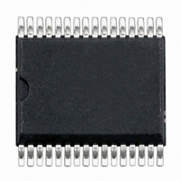
CPC5621ATR Clare, CPC5621ATR Datasheet - Page 4

CPC5621ATR
Manufacturer Part Number
CPC5621ATR
Description
IC LITELINK III FULL RING 32SOIC
Manufacturer
Clare
Series
LITELINK® IIIr
Specifications of CPC5621ATR
Function
Data Access Arrangement (DAA)
Number Of Circuits
1
Voltage - Supply
3 V ~ 5.5 V
Current - Supply
9mA
Power (watts)
1W
Operating Temperature
-40°C ~ 85°C
Mounting Type
Surface Mount
Package / Case
32-SOIC (7.5mm Width)
Includes
Caller ID Signal Reception Function, Full-Wave Ring Detection
For Use With
CLA165 - LITELINK III EVALUATION BOARDCLA164 - LITELINK III EVALUATION BOARD
Lead Free Status / RoHS Status
Lead free / RoHS Compliant
Interface
-
Other names
CLA321TR
CPC5621ATR
CPC5621ATR
Available stocks
Company
Part Number
Manufacturer
Quantity
Price
Part Number:
CPC5621ATR
Manufacturer:
LITELINK
Quantity:
20 000
CPC5620/CPC5621
1.2 Performance
4
DC Characteristics
Operating Voltage V
Operating Current I
Operating Voltage V
Operating Current I
On-hook Characteristics
Metallic DC Resistance
Longitudinal DC Resistance
Ringing Signal Detect Level
Ringing Signal Detect Level
Snoop Circuit Frequency Response
Snoop Circuit CMRR
Ringer Equivalence
Longitudinal Balance
Off-Hook Characteristics
AC Impedance
Longitudinal Balance
Return Loss
Transmit and Receive Characteristics
Frequency Response
Transhybrid Loss
Transmit and Receive Insertion Loss
Average In-band Noise
Harmonic Distortion
Transmit Level
Receive Level
RX+/RX- Output Drive Current
TX+/TX- Input Impedance
Isolation Characteristics
Isolation Voltage
Surge Rise Time
MODE, OH, and CID Control Logic Inputs
Input Low Voltage
Input High Voltage
High Level Input Current
Low Level Input Current
RING Output Logic Levels
Output High Voltage
Output Low Voltage
Specifications subject to change without notice. All performance characteristics based on the use of Clare application circuits. Functional operation of the device at
conditions beyond those specified here is not implied. All specifications at 25°C and V
1) This parameter is layout and component tolerance dependent.
Parameter
DD
DDL
DD
DDL
1
1
Minimum
V
DD
3000
2000
166
-0.4
3.0
2.8
2.0
10
10
28
60
40
30
60
5
-
-
-
-
-
-
-
-
-
-
-
-
-
-
-
-
-0.4
Typical
0.1B
-126
600
-80
40
26
36
90
9
7
0
-
-
-
-
-
-
-
-
-
-
-
-
-
-
-
-
-
-
-
-
-
www.clare.com
Maximum
>4000
4000
-120
-120
5.50
120
3.2
0.4
2.2
2.2
0.5
0.8
0.4
13
8
-
-
-
-
-
-
-
-
-
-
-
-
-
-
-
-
-
DD
= 5V unless otherwise noted.
dBm/Hz
V/μS
REN
Unit
V
V
V
V
V
MΩ
MΩ
mA
mA
mA
kΩ
V
V
μA
μA
Hz
dB
dB
dB
dB
Hz
dB
dB
dB
Ω
V
V
rms
rms
P-P
P-P
rms
V
V
IH
IL
Conditions
Low-voltage side
Low-voltage side
Line side, derived from tip and ring
Line side, drawn from tip and ring while off-hook
Tip to ring, 100 V
150 V
68 Hz ring signal applied tip to ring
15 Hz ring signal applied tip to ring
-3 dB corner frequency @ 166 Hz, in Clare
application circuit
120 V
and ring
Per FCC part 68
Tip to ring, using resistive termination application
circuit
Per FCC part 68
Into 600Ω at 1800 Hz
-3 dB corner frequency 30 Hz
Into 600Ω at 1800 Hz, with C18 in the resistive
termination application circuit
30 Hz to 4 kHz, for resistive termination application
circuit with MODE de-asserted and for reactive
termination application circuit with MODE
asserted.
4 kHz flat bandwidth
-3 dBm, 600 Hz, 2
Single-tone sine wave. Or 0 dBm into 600Ω
Single-tone sine wave. Or 0 dBm into 600Ω
Sink and source
Line side to low-voltage side, one minute duration
No damage via tip and ring
V
V
I
I
OUT
OUT
IN
IN
≤
= GND
= -400 μA
= 1 mA
DC
rms
V
DD
applied from tip and ring to Earth ground
60 Hz common-mode signal across tip
DC
nd
applied
harmonic
R04


