ISL54004IRTZ Intersil, ISL54004IRTZ Datasheet
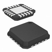
IC AMP AUDIO PWR 1.23W AB 20TQFN

ISL54004IRTZ

Manufacturer Part Number
ISL54004IRTZ
Description
IC AMP AUDIO PWR 1.23W AB 20TQFN
Manufacturer
Intersil
Type
Class ABr
Datasheet

Specifications of ISL54004IRTZ

Output Type
1-Channel (Mono) with Stereo Headphones
Max Output Power X Channels @ Load
1.23W x 1 @ 8 Ohm; 215mW x 2 @ 16 Ohm
Voltage - Supply
2.7 V ~ 5.5 V
Features
Depop, Shutdown, Thermal Protection
Mounting Type
Surface Mount
Package / Case
20-TQFN
Lead Free Status / RoHS Status
Lead free / RoHS Compliant
Integrated Audio Amplifier Systems
The Intersil ISL54004 device is an integrated audio power
amplifier system that combines a mono BTL amplifier and
stereo headphone amplifiers in a single device. It can operate
from a single +2.7V to +5V power supply and is offered in a
20 Ld 4x4 TQFN package. Targeted applications include
handheld equipment such as cell-phones, MP3 players, and
games/toys.
The ISL54004 part contains one class AB BTL type power
amplifier for driving an 8Ω mono speaker and two class AB
headphone amplifiers for driving 16Ω or 32Ω headphone
speakers.
The BTL when using a 5V supply is capable of delivering
800mW (typ) with 0.4% THD+N and 941mW (typ) with 1%
THD+N of continuous average power into an 8Ω BTL speaker
load.
Each headphone amplifier when using a 5V supply is capable
of delivering 50mW (typ) with 0.3% THD+N and 94mW (typ)
with 1% THD+N of continuous average power into a 32Ω
headphone speaker.
When in Mono mode the part automatically mixes the left and
right audio inputs and sends the combined signal to the BTL
driver. In Headphone Mode, the active right channel input is
sent to the right headphone speaker and the active left
channel is sent to the left headphone speaker.
The ISL54004 has a four-level programmable gain stage to
boost the audio signal. The part requires no external gain
setting resistors.
The ISL54004 part features headphone sense input circuitry
that detects when a headphone jack has been inserted and
automatically switches the audio inputs from the mono BTL
output driver to the headphone drivers. The part also has a
logic control pin that can override the headphone sense
input circuitry.
The part also features low power shutdown, thermal
overload protection and click and pop suppression. The click
and pop circuitry prevents click and pops at the speakers
when transitioning in and out of shutdown.
®
1
Data Sheet
1-888-INTERSIL or 1-888-468-3774
CAUTION: These devices are sensitive to electrostatic discharge; follow proper IC Handling Procedures.
Features
• Class AB 94mW Headphone Amplifiers and 941mW Mono
• THD+N at 1kHz, 800mW into 8Ω BTL . . . . . . . . . . . . . .0.4%
• THD+N at 1kHz, 15mW into 32Ω Headphone . . . . . . .0.07%
• THD+N at 1kHz, 50mW into 32Ω Headphone . . . . . . . .0.3%
• Single Supply Operation . . . . . . . . . . . . . . . . .+2.7V to +5.5V
• Headphone Sense Input and Low Power Shutdown
• Thermal Shutdown Protection
• “Click and Pop” Suppression Circuitry
• Selectable Gain Settings
• TTL Logic-Compatible
• Available in 20 Ld 4x4 TQFN
• Pb-Free (RoHS Compliant)
Applications
• Battery-powered, Handheld, and Portable Equipment
• Desktop Computers
Simplified Block Diagram
BTL Speaker Amplifier
- Cellular/mobile Phones
- PDA’s, MP3 Players, DVD Players, Cameras
- Laptops, Notebooks, Palmtops
- Handheld Games and Toys
October 30, 2007
R
L
All other trademarks mentioned are the property of their respective owners.
|
Intersil (and design) is a registered trademark of Intersil Americas Inc.
CLICK
GS0
GS1
AND
POP
HO
SD
ISL54004
GAIN
Copyright Intersil Americas Inc. 2007. All Rights Reserved
CONTROL
LOGIC
SWITCHER
ROUTER/
SHUTDOWN
THERMAL
BIAS
V
DD
ISL54004
FN6513.2

Related parts for ISL54004IRTZ

ISL54004IRTZ Summary of contents

Page 1

... ISL54004 CAUTION: These devices are sensitive to electrostatic discharge; follow proper IC Handling Procedures. | 1-888-INTERSIL or 1-888-468-3774 Intersil (and design registered trademark of Intersil Americas Inc. Copyright Intersil Americas Inc. 2007. All Rights Reserved All other trademarks mentioned are the property of their respective owners. ISL54004 FN6513 ...

Page 2

... PART PART RANGE NUMBER MARKING (°C) ISL54004IRTZ* 540 04IRTZ - 4x4 TQFN (Note) *Add “-T” suffix for tape and reel. Please refer to TB347 for details on reel specifications. NOTE: These Intersil Pb-free plastic packaged products employ special Pb-free material sets; molding compounds/die attach materials ...

Page 3

... Thermal Information Thermal Resistance (Typical, Note 4x4 TQFN Package . . . . . . . . . . Maximum Junction Temperature . . . . . . . . . . . . . . . . . . . . . +150°C Maximum Storage Temperature Range . . . . . . . . . . . -65°C to +150°C Pb-free reflow profile . . . . . . . . . . . . . . . . . . . . . . . . . see link below http://www.intersil.com/pbfree/Pb-FreeReflow.asp Test Conditions +5V, GND = 0V 1µ terminated between SPK+ and SPK- for BTL driver and between Hp_ and ...

Page 4

Electrical Specifications - 5V Supply PARAMETER Total Harmonic Distortion + Noise THD Max Output Voltage Swing OUT L Signal to Noise Ratio, SNR R L Output Noise Weight filter ...

Page 5

Electrical Specifications - 3.6V Supply PARAMETER GENERAL Quiescent Supply Current coupled to GND (0.1µF) Shutdown Supply Current (BTL) and R (0.1µF) BTL AMPLIFIER DRIVER ...

Page 6

... LEFT AUDIO MICRO CONTROLLER Detailed Description The Intersil ISL54004 device is an integrated audio power amplifier system designed to provide quality audio, while requiring minimal external components. Low 0.4% THD+N ensures clean, low distortion amplification of the audio signals designed to operate from a single +2.7V to +5V power supply ...

Page 7

The “Typical Application Circuit and Block Diagram” for this device is provided on page 6. The “Truth Table” for the device is provided on page 2. DC Bias Voltage The ISL54004 has internal DC bias circuitry which DC offsets the ...

Page 8

Low Power Shutdown With a logic “1” at the SD control pin the device enters the low power shutdown state. When in shutdown the BTL and headphone amplifiers go into an high impedance state and I supply current is reduced ...

Page 9

Typical Performance Curves 10 5.00 BTL R = 8Ω 1kHz 2.00 1.00 0.50 0.20 0.10 0.05 0.02 0.01 10m 20m 50m 100m OUTPUT POWER (W) FIGURE 3. THD+N vs OUTPUT POWER 0.20 V ...

Page 10

Typical Performance Curves 32Ω 30mW O 0.20 0.10 0.05 0.02 0. 100 200 500 1k FREQUENCY (Hz) FIGURE 9. THD+N vs FREQUENCY 0. ...

Page 11

Typical Performance Curves 10 5. 32Ω 1kHz 1.00 0.50 0.20 0.10 0.05 0.02 0.01 10m 20m 30m 40m OUTPUT POWER (W) FIGURE 15. THD+N vs OUTPUT POWER 10.0 V ...

Page 12

Typical Performance Curves -20 - -24 BTL -26 - 200MV RIPPLE P-P -30 -32 -34 -36 -38 -40 -42 -44 -46 -48 -50 -52 -54 -56 -58 -60 -62 -64 -66 -68 -70 10 ...

Page 13

... Accordingly, the reader is cautioned to verify that data sheets are current before placing orders. Information furnished by Intersil is believed to be accurate and reliable. However, no responsibility is assumed by Intersil or its subsidiaries for its use; nor for any infringements of patents or other rights of third parties which may result from its use ...

Related keywords