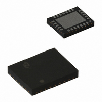
LM4868LQ National Semiconductor, LM4868LQ Datasheet - Page 19

LM4868LQ
Manufacturer Part Number
LM4868LQ
Description
IC AMP AUDIO PWR 3W STER 24LLP
Manufacturer
National Semiconductor
Series
Boomer®r
Type
Class ABr
Datasheet
1.LM4868LQ.pdf
(28 pages)
Specifications of LM4868LQ
Output Type
2-Channel (Stereo) with Stereo Headphones
Max Output Power X Channels @ Load
3W x 2 @ 3 Ohm; 208mW x 2 @ 16 Ohm
Voltage - Supply
2 V ~ 5.5 V
Features
Depop, Input Multiplexer, Shutdown, Thermal Protection
Mounting Type
Surface Mount
Package / Case
24-LLP
Lead Free Status / RoHS Status
Lead free / RoHS Compliant
Other names
LM4868LQTR
Available stocks
Company
Part Number
Manufacturer
Quantity
Price
Part Number:
LM4868LQX
Manufacturer:
NS/国半
Quantity:
20 000
Application Information
and an
As mentioned in the Selecting Proper External Compo-
nents section, R
amplifier’s lower bandpass frequency limit. Find the coupling
capacitor’s value using Equation (12).
The result is
Use a 0.39µF capacitor, the closest standard value.
The product of the desired high frequency cutoff (100kHz in
this example) and the differential gain A
1/(2π
i
and C
f
H
*
f
= 20kHz x 5 = 100kHz
L
20kΩ
i
= 100Hz/5 = 20Hz
create a highpass filter that sets the
C
i
≥ 1/(2πR
*
20Hz) = 0.397µF
i
f
L
FIGURE 9. Recommended LQ PC Board Layout:
)
VD
(Continued)
, determines the
Component-Side Silkscreen
(12)
(13)
(14)
(15)
19
upper passband response limit. With A
100kHz, the closed-loop gain bandwidth product (GBWP) is
300kHz. This is less than the LM4868’s 3.5MHz GBWP. With
this margin, the amplifier can be used in designs that require
more differential gain while avoiding performance,restricting
bandwidth limitations.
RECOMMENDED PRINTED CIRCUIT BOARD LAYOUT
Figures 9 through 13 show the recommended four-layer PC
board layout that is optimized for the 24-pin LQ-packaged
LM4868 and associated external components. Figures 14
through 18 show the recommended four-layer PC board
layout that is optimized for the 24-pin MTE-packaged
LM4868 and associated external components. Figures 19
through 21 show the recommended two-layer PC board
layout that is optimized for the 20-pin MT-packaged LM4868
and associated external components. These circuits are de-
signed for use with an external 5V supply and 4Ω speakers
(or greater) for the MT-packaged LM4868 or 3Ω speakers (or
greater) for the LQ- and MTE-packaged LM4868.
These circuit boards are easy to use. Apply 5V and ground to
the board’s V
speakers between the board’s −OUTA and +OUTA and
OUTB and +OUTB pads.
DD
and GND pads, respectively. Connect 4Ω
20026778
VD
= 3 and f
www.national.com
H
=


