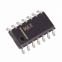
MAX4386EESD+ Maxim Integrated Products, MAX4386EESD+ Datasheet - Page 9

MAX4386EESD+
Manufacturer Part Number
MAX4386EESD+
Description
IC OP AMP R-R SNGL 14-SOIC
Manufacturer
Maxim Integrated Products
Datasheet
1.MAX4386EESD.pdf
(13 pages)
Specifications of MAX4386EESD+
Applications
Voltage Feedback
Output Type
Rail-to-Rail
Number Of Circuits
4
-3db Bandwidth
230MHz
Slew Rate
450 V/µs
Current - Supply
5.5mA
Current - Output / Channel
55mA
Voltage - Supply, Single/dual (±)
4.5 V ~ 5.5 V
Mounting Type
Surface Mount
Package / Case
14-SOIC (0.154", 3.90mm Width)
Number Of Channels
4
Voltage Gain Db
63 dB
Common Mode Rejection Ratio (min)
70 dB
Input Offset Voltage
20 mV
Operating Supply Voltage
5 V
Maximum Power Dissipation
667 mW
Maximum Operating Temperature
+ 85 C
Mounting Style
SMD/SMT
Minimum Operating Temperature
- 40 C
Lead Free Status / RoHS Status
Lead free / RoHS Compliant
The input common-mode range extends from (V
200mV) to (V
rejection. Beyond this range, the amplifier output is a
nonlinear function of the input, but does not undergo
phase reversal or latchup.
The output swings to within 50mV of either power-sup-
ply rail with a 2kΩ load. The input ground sensing and
the rail-to-rail output substantially increase the dynamic
range. The input can swing 2.95V
can swing 4.9V
The MAX4385E/MAX4386E are optimized for AC perfor-
mance and do not drive highly reactive loads, which
decreases phase margin and may produce excessive
ringing and oscillation. Figure 2 shows a circuit that
eliminates this problem. Figure 3 is a graph of the
Optimal Isolation Resistor (R
Figure 4 shows how a capacitive load causes exces-
sive peaking of the amplifier’s frequency response if
the capacitor is not isolated from the amplifier by a
resistor. A small isolation resistor (usually 10Ω to 15Ω)
placed before the reactive load prevents ringing and
oscillation. At higher capacitive loads, the interaction of
the load capacitance and the isolation resistor controls
the AC performance. Figure 5 shows the effect of a
15Ω isolation resistor on closed-loop response.
Figure 2. Driving a Capacitive Load Through an Isolation Resistor
Output Capacitive Loading and Stability
Rail-to-Rail Outputs and ±15kV ESD Protection
Low-Cost, 230MHz, Single/Quad Op Amps with
R
V
G
IN
CC
P-P
- 2.25V) with excellent common-mode
_______________________________________________________________________________________
with minimal distortion.
MAX438_E
Ground-Sensing Inputs
R
F
Rail-to-Rail Outputs,
S
) vs. Capacitive Load.
P-P
R
ISO
and the output
C
L
V
OUT
EE
-
Figure 3. Isolation Resistance vs. Capacitive Load
Figure 4. Small-Signal Gain vs. Frequency with Load
Capacitance and No Isolation Resistor
Figure 5. Small-Signal Gain vs. Frequency with Load
Capacitance and
-1
-2
-3
-4
-5
-6
-7
-1
-2
-3
-4
16
15
14
13
12
11
10
3
2
1
0
6
5
4
3
2
1
0
9
100k
100k
0
27Ω Isolation Resistor
R
ISO
50
= 15Ω
100
ISOLATION RESISTANCE
vs. CAPACITIVE LOAD
1M
1M
150
C
L
C
FREQUENCY (Hz)
FREQUENCY (Hz)
= 120pF
200
L
C
C
= 68pF
L
LOAD
= 10pF
10M
250
10M
C
(pF)
L
300
= 5pF
350
100M
100M
C
L
400
C
= 47pF
L
= 15pF
450 500
1G
1G
9


