ISL59448IAZ-T7 Intersil, ISL59448IAZ-T7 Datasheet - Page 3
ISL59448IAZ-T7
Manufacturer Part Number
ISL59448IAZ-T7
Description
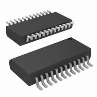
IC AMP MUX 2:1 500MHZ 24-QSOP
Manufacturer
Intersil
Datasheet
1.ISL59448IAZ-T7.pdf
(14 pages)
Specifications of ISL59448IAZ-T7
Applications
2:1 Multiplexer-Amplifier
Number Of Circuits
3
-3db Bandwidth
570MHz
Slew Rate
1600 V/µs
Current - Supply
31mA
Current - Output / Channel
180mA
Mounting Type
Surface Mount
Package / Case
24-QSOP
Lead Free Status / RoHS Status
Lead free / RoHS Compliant
Available stocks
Company
Part Number
Manufacturer
Quantity
Price
Company:

Part Number:
ISL59448IAZ-T7
Manufacturer:
Intersil
Quantity:
800


Absolute Maximum Ratings
Supply Voltage (V+ to V-). . . . . . . . . . . . . . . . . . . . . . . . . . . . . . . 11V
Input Voltage . . . . . . . . . . . . . . . . . . . . . . . . . . . . V- -0.5V, V+ +0.5V
Supply Turn-on Slew Rate . . . . . . . . . . . . . . . . . . . . . . . . . . . 1V/µs
Digital & Analog Input Current (Note 1) . . . . . . . . . . . . . . . . . . 50mA
Output Current (Continuous) . . . . . . . . . . . . . . . . . . . . . . . . . . 50mA
ESD Rating
CAUTION: Stresses above those listed in “Absolute Maximum Ratings” may cause permanent damage to the device. This is a stress only rating and operation of the
device at these or any other conditions above those indicated in the operational sections of this specification is not implied.
NOTE:
IMPORTANT NOTE: All parameters having Min/Max specifications are guaranteed. Typical values are for information purposes only. Unless otherwise noted, all tests
are at the specified temperature and are pulsed tests, therefore: T
Electrical Specifications
GENERAL
LOGIC
AC GENERAL
1. If an input signal is applied before the supplies are powered up, the input current must be limited to these maximum values.
PARAMETER
Human Body Model (Per MIL-STD-883 Method 3015.7). . . .2500V
Machine Model . . . . . . . . . . . . . . . . . . . . . . . . . . . . . . . . . . .300V
+I
+
-I
-
I
A
I
S
Off - ISO
S
S
S
CL
PSRR
R
R
V
Disabled
Enabled
Disabled
I
Xtalk
Enabled
V
OUT
R
V
V
dG
OUT
OUT
OUT
I
dP
I
Ib
OS
IH
IL
or A
IH
IN
IL
V
Enabled Supply Current
Enabled Supply Current
Disabled Supply Current
Disabled Supply Current
Positive and Negative Output Swing
Output Current
Output Offset Voltage
Input Bias Current
HIZ Output Resistance
Enabled Output Resistance
Input Resistance
Voltage Gain
Input High Voltage (Logic Inputs)
Input Low Voltage (Logic Inputs)
Input High Current (Logic Inputs)
Input Low Current (Logic Inputs)
Power Supply Rejection Ratio
Channel to Channel Crosstalk
Off-state Isolation
Differential Gain Error
Differential Phase Error
DESCRIPTION
3
V+ = +5V, V- = -5V, GND = 0V, T
specified.
(T
A
= 25°C)
J
= T
C
No load, V
No load, V
No load, V
No load, V
V
V
V
HIZ = Logic High
HIZ = Logic Low
V
R
V
V
DC, PSRR V+ & V- combined
V
f = 10MHz, ChX-Ch Y-Talk
V
f = 10MHz, Ch-Ch Off Isolation
V
NTC-7, R
NTC-7, R
= T
IN
IN
IN
IN
L
H
L
OUT
IN
IN
ISL59448
A
= 500Ω
= 0V
= 5V
= ±2.5V; R
= 1Vp-p; C
= 1Vp-p; C
= 0.825V R
= 0V
=
A
±
= 25°C, Vout = ±2V
= 0dBm
1.75V
L
L
IN
IN
IN
IN
= 150, C
= 150, C
= 0V, Enable Low
= 0V, Enable Low
= 0V, Enable High
= 0V, Enable High
CONDITIONS
Storage Temperature Range . . . . . . . . . . . . . . . . . .-65°C to +150°C
Ambient Operating Temperature . . . . . . . . . . . . . . . .-40°C to +85°C
Operating Junction Temperature . . . . . . . . . . . . . . .-40°C to +125°C
Power Dissipation . . . . . . . . . . . . . . . . . . . . . . . . . . . . . See Curves
L
L
L
L
= 500Ω
= 1.1pF
= 1.1pF
= 10Ω
L
L
= 1.1pF
= 1.1pF
P-P
& R
L
= 500Ω to GND, C
MIN
±3.1
1.94
-0.1
±80
700
200
-32
2.3
-40
27
52
-3
-3
L
0.015
0.015
= 0pF, unless otherwise
TYP
±3.9
1.98
900
258
-29
-25
2.7
0.2
0.8
31
10
72
88
72
-2
2
2.035
MAX
±180
1150
319
-25
3.3
0.1
-10
35
-1
3
March 29, 2006
FN6160.2
UNIT
MΩ
V/V
mA
mA
mA
mA
mA
mV
µA
µA
µA
dB
dB
dB
%
V
Ω
Ω
V
V
°
Related parts for ISL59448IAZ-T7
Image
Part Number
Description
Manufacturer
Datasheet
Request
R

Part Number:
Description:
Multiplexing Amplifier
Manufacturer:
Intersil Corporation
Datasheet:
Part Number:
Description:
Intersil Corporation [CMOS Serial Controller Interface]
Manufacturer:
Intersil Corporation
Datasheet:
Part Number:
Description:
Manufacturer:
Intersil Corporation
Datasheet:
Part Number:
Description:
357-036-542-201 CARDEDGE 36POS DL .156 BLK LOPRO
Manufacturer:
Intersil Corporation
Datasheet:
Part Number:
Description:
1024-Word x 4-Bit LSI Static RAM
Manufacturer:
Intersil Corporation
Datasheet:
Part Number:
Description:
General Purpose NPN Transistor Arrays FN341.4
Manufacturer:
Intersil Corporation
Datasheet:
Part Number:
Description:
CMOS 16-Bit Microprocessor
Manufacturer:
Intersil Corporation
Datasheet:
Part Number:
Description:
Manufacturer:
Intersil Corporation
Datasheet:
Part Number:
Description:
Manufacturer:
Intersil Corporation
Datasheet:
Part Number:
Description:
Manufacturer:
Intersil Corporation
Datasheet:
Part Number:
Description:
Manufacturer:
Intersil Corporation
Datasheet:
Part Number:
Description:
CMOS 6-Bit Latch and Decoder Memory Interfaces
Manufacturer:
Intersil Corporation
Datasheet:
Part Number:
Description:
CA3046General Purpose NPN Transistor Arrays
Manufacturer:
Intersil Corporation
Datasheet:
Part Number:
Description:
Manufacturer:
Intersil Corporation
Datasheet:
Part Number:
Description:
TR909 DLC/FLC SLIC with Low Power Standby
Manufacturer:
Intersil Corporation
Datasheet: