AD534LD Analog Devices Inc, AD534LD Datasheet - Page 7
AD534LD
Manufacturer Part Number
AD534LD
Description
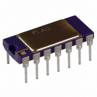
IC PREC MULTIPLIER 14-CDIP
Manufacturer
Analog Devices Inc
Specifications of AD534LD
Rohs Status
RoHS non-compliant
Function
Analog Multiplier/Divider
Number Of Bits/stages
4-Quadrant
Package / Case
14-CDIP (0.300", 7.62mm)
No. Of Multipliers / Dividers
1
No. Of Amplifiers
4
Supply Voltage Range
± 8V To ± 18V
Slew Rate
20V/µs
Operating Temperature Range
0°C To +70°C
Digital Ic Case Style
TO-116
Ic Function
Precision IC Multiplier
No. Of Pins
14
Svhc
No SVHC (15-Dec-2010)
Rohs Compliant
No
Analogue Multiplexer Type
4-Quadrant
Lead Free Status / RoHS Status
Contains lead / RoHS non-compliant
Available stocks
Company
Part Number
Manufacturer
Quantity
Price


OPERATION AS A DIVIDER
The AD535, a pin-for-pin functional equivalent to the AD534,
has guaranteed performance in the divider and square-rooter
configurations and is recommended for such applications.
Figure 6 shows the connection required for division. Unlike
earlier products, the AD534 provides differential operation on
both numerator and denominator, allowing the ratio of two
floating variables to be generated. Further flexibility results from
access to a high impedance summing input to Y
dividers based on the use of a multiplier in a feedback loop, the
bandwidth is proportional to the denominator magnitude, as
shown in Figure 23.
Without additional trimming, the accuracy of the AD534K
and L is sufficient to maintain a 1% error over a 10 V to 1 V
denominator range. This range may be extended to 100:1 by
simply reducing the X offset with an externally generated trim
voltage (range required is 3.5 mV max) applied to the unused
X input (see Figure 1). To trim, apply a ramp of +100 mV to
+V at 100 Hz to both X
ment, otherwise reverse the signal polarity) and adjust the trim
voltage to minimize the variation in the output.*
Since the output will be near +10 V, it should be ac-coupled for
this adjustment. The increase in noise level and reduction in
bandwidth preclude operation much beyond a ratio of 100 to 1.
As with the multiplier connection, overall gain can be intro-
duced by inserting a simple attenuator between the output and
Y
the AD534 are utilized in the percentage-computer application
shown in Figure 12. This configuration generates an output
proportional to the percentage deviation of one variable (A) with
respect to a reference variable (B), with a scale of one volt per
percent.
*See the AD535 data sheet for more details.
REV. B
2
OPTIONAL
SUMMING
terminal. This option, and the differential-ratio capability of
(DENOMINATOR)
10V PK
INPUT
+12V PK
X INPUT
+10V FS
Figure 6. Basic Divider Connection
+
–
SF
X
X
Y
Y
1
2
1
2
AD534
1
and Z
OUT
+V
–V
Z
Z
1
2
S
1
S
(if X
Z INPUT
(NUMERATOR)
+15V
–15V
2
10V FS,
is used for offset adjust-
12V PK
OUTPUT,
=
1
10V (Z
. As with all
(X
1
– X
2
– Z
2
12V PK
)
1
)
+ Y
1
–7–
OPERATION AS A SQUARE ROOTER
The operation of the AD534 in the square root mode is shown
in Figure 7. The diode prevents a latching condition which
could occur if the input momentarily changes polarity. As
shown, the output is always positive; it may be changed to a
negative output by reversing the diode direction and interchang-
ing the X inputs. Since the signal input is differential, all combi-
nations of input and output polarities can be realized, but
operation is restricted to the one quadrant associated with each
combination of inputs.
In contrast to earlier devices, which were intolerant of capacitive
loads in the square root modes, the AD534 is stable with all
loads up to at least 1000 pF. For critical applications, a small
adjustment to the Z input offset (see Figure 1) will improve
accuracy for inputs below 1 V.
X,
OPTIONAL
SUMMING
10V PK
INPUT,
Figure 7. Square-Rooter Connection
SF
X
X
Y
Y
1
2
1
2
AD534
OUT
+V
–V
Z
Z
S
2
1
S
+15V
–
+
–15V
Z INPUT
10V FS
12V PK
REVERSE
THIS AND X
INPUTS FOR
NEGATIVE
OUTPUTS
OUTPUT,
=
AD534
10V (Z
R
(MUST BE
PROVIDED)
L
2
12V PK
– Z
1
) +X
2
Related parts for AD534LD
Image
Part Number
Description
Manufacturer
Datasheet
Request
R

Part Number:
Description:
±1.7g Dual-Axis IMEMS Accelerometer Evaluation Board
Manufacturer:
Analog Devices Inc
Datasheet:

Part Number:
Description:
Inertial Sensor Evaluation System
Manufacturer:
Analog Devices Inc
Datasheet:
Part Number:
Description:
Manufacturer:
Analog Devices Inc
Datasheet:
Part Number:
Description:
Manufacturer:
Analog Devices Inc
Datasheet:
Part Number:
Description:
Manufacturer:
Analog Devices Inc
Datasheet:
Part Number:
Description:
Manufacturer:
Analog Devices Inc
Datasheet:
Part Number:
Description:
Manufacturer:
Analog Devices Inc
Datasheet:
Part Number:
Description:
Manufacturer:
Analog Devices Inc
Datasheet:
Part Number:
Description:
Manufacturer:
Analog Devices Inc
Datasheet:
Part Number:
Description:
Manufacturer:
Analog Devices Inc
Datasheet:
Part Number:
Description:
Manufacturer:
Analog Devices Inc
Datasheet:
Part Number:
Description:
Manufacturer:
Analog Devices Inc
Datasheet:
Part Number:
Description:
Manufacturer:
Analog Devices Inc
Datasheet: