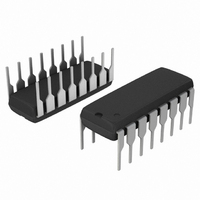
SA572NG ON Semiconductor, SA572NG Datasheet - Page 6

SA572NG
Manufacturer Part Number
SA572NG
Description
IC COMPANDOR 2CHAN GAIN 16-DIP
Manufacturer
ON Semiconductor
Type
Compandorr
Datasheet
1.SA572DTBR2.pdf
(12 pages)
Specifications of SA572NG
Applications
Automatic Level Control, Stereo Expander
Mounting Type
Through Hole
Package / Case
16-DIP (0.300", 7.62mm)
Maximum Operating Temperature
+ 85 C
Mounting Style
Through Hole
Minimum Operating Temperature
- 40 C
Lead Free Status / RoHS Status
Lead free / RoHS Compliant
Other names
SA572NG
SA572NGOS
SA572NGOS
Available stocks
Company
Part Number
Manufacturer
Quantity
Price
Part Number:
SA572NG
Manufacturer:
ON/安森美
Quantity:
20 000
Buffer Amplifier
and slow recovery time for a tone burst input. The fast
attack time reduces transient channel overload but also
causes low-frequency ripple distortion. The low-frequency
ripple distortion can be improved with the slow recovery
time. If different attack times are implemented in
corresponding frequency spectrums in a split band audio
system, high quality performance can be achieved. The
buffer amplifier is designed to make this feature available
with minimum external components. Referring to
Figure 5, the rectifier output current is mirrored into the
input and output of the unipolar buffer amplifier A
Q
accuracy and provide common-mode bias for A
positive-going input signal, the buffer amplifier acts like a
voltage-follower. Therefore, the output impedance of A
makes the contribution of capacitor C
insignificant. Neglecting diode impedance, the gain Ga(t)
for DG can be expressed as follows:
8
In audio systems, it is desirable to have fast attack time
, Q
9
and Q
10
. Diodes D
Q
17
11
and D
Q
I
R
8
+
C
V IN
Q
R
12
A
9
improve tracking
R
10kW
Figure 5. Buffer Amplifier Schematic
to attack time
D
Q
11
10
3
IR
3
through
1
. For a
V+
http://onsemi.com
D
−
+
12
TRACKING
3
A3
TRIM
6
Ga(t) + (Ga
Ga
Ga
t
where t
internal resistor. Diode D
for a negative-going signal if the value of capacitor C
larger than capacitor C
on C
the dynamic gain G
where t
internal resistor. The gain control current is mirrored to the
gain cell through Q
bias current of A
tracking trim pin into A
A
= R
INT
FNL
D
R
15
A
= Initial Gain
• R
= Final Gain
C
• C
R
A
R
G
G
R
is the recovery time constant and R
is the attack time constant and R
R
R
A
. If the diode impedance is assumed negligible,
(t) + (G
(t) + (G
= 10 k
INT
t
10kW
IR
R
D
2
* Ga
= R
13
2
Q
14
W
14
R
R
and A
. The low level gain errors due to input
I
RINT
RINT
Q
• C
• C
(t) for DG is expressed as follows:
= 2IR
A
3
FNL
. The recovery time depends only
R
A
with a current source of "3.0 mA.
15
* G
* G
) e
= 10 kW • C
2
3
opens the feedback loop of A
*t
can be trimmed through the
t A
Q
Q
X2
X2
RFNL
RFNL
) Ga
16
18
) e
) e
R
*t
*t
FNL
t R
t R
) G
) G
A
RFNL
RFNL
R
is a 10 kW
is a 10 kW
R
is
3


