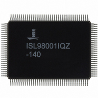
ISL98001IQZ-140 Intersil, ISL98001IQZ-140 Datasheet - Page 19

ISL98001IQZ-140
Manufacturer Part Number
ISL98001IQZ-140
Description
IC TRPL VIDEO DIGITIZER 128-MQFP
Manufacturer
Intersil
Type
Video Digitizerr
Datasheet
1.ISL98001IQZ-140.pdf
(31 pages)
Specifications of ISL98001IQZ-140
Applications
Monitors, Projectors, Players
Mounting Type
Surface Mount
Package / Case
128-MQFP, 128-PQFP
Rohs Compliant
Yes
Lead Free Status / RoHS Status
Lead free / RoHS Compliant
Available stocks
Company
Part Number
Manufacturer
Quantity
Price
Automatic Black Level Compensation (ABLC™)
and Gain Control
Traditional video AFEs have an offset DAC prior to the ADC,
to both correct for offsets on the incoming video signals and
add/subtract an offset for user “brightness control” without
sacrificing the 8-bit dynamic range of the ADC. This solution
is adequate, but it places significant requirements on the
system's firmware, which must execute a loop that detects
the black portion of the signal and then servos the offset
DACs until that offset is nulled (or produces the desired ADC
output code). Once this has been accomplished, the offset
(both the offset in the AFE and the offset of the video card
generating the signal) is subject to drift - the temperature
inside a monitor or projector can easily change +50°C
between power-on/offset calibration on a cold morning and
the temperature reached once the monitor and the monitor's
environment have reached steady state. Offset can drift
significantly over +50°C, reducing image quality and
requiring that the user do a manual calibration once the
monitor has warmed up.
In addition to drift, many AFEs exhibit interaction between
the offset and gain controls. When the gain is changed, the
magnitude of the offset is changed as well. This again
increases the complexity of the firmware as it tries to
optimize gain and offset settings for a given video input
signal. Instead of adjusting just the offset, then the gain, both
have to be adjusted interactively until the desired ADC
output is reached.
The ISL98001 simplifies offset and gain adjustment and
completely eliminates offset drift using its Automatic Black
Level Compensation (ABLC™) function. ABLC monitors the
black level and continuously adjusts the ISL98001's 10-bit
offset DACs to null out the offset. Any offset, whether due to
the video source or the ISL98001's analog amplifiers, is
eliminated with 10-bit (1/4 of an ADC LSB) accuracy. Any drift
is compensated for well before it can have a visible effect.
Manual offset adjustment control is still available - an 8-bit
register allows the firmware to adjust the offset ±64 codes in
exactly 1 ADC LSB increments. And gain is now completely
independent of offset - adjusting the gain no longer affects the
offset, so there is no longer a need to program the firmware to
cope with interactive offset and gain controls.
Finally, there should be no concerns over ABLC itself
introducing visible artifacts; it doesn't. ABLC functions at a
very low frequency, changing the offset in 1/4 LSB
increments, so it can't cause visible brightness fluctuations.
And once ABLC is locked, if the offset doesn't drift, the DACs
won't change. If desired, ABLC can be disabled, allowing the
firmware to work in the traditional way, with 10-bit offset
DACs under the firmware's control.
Gain and Offset Control
To simplify image optimization algorithms, the ISL98001
features fully-independent gain and offset adjustment.
19
ISL98001
Changing the gain does not affect the DC offset, and the
weight of an Offset DAC LSB does not vary depending on
the gain setting.
The full-scale gain is set in the three 8-bit registers
(0x06-0x08). The ISL98001 can accept input signals with
amplitudes ranging from 0.35V
The offset controls shift the entire RGB input range, changing
the input image brightness. Three separate registers provide
independent control of the R, G, and B channels. Their
nominal setting is 0x80, which forces the ADC to output code
0x00 (or 0x80 for the R (Pr) and B (Pb) channels in YPbPr
mode) during the back porch period when ABLC is enabled.
Functional Description
Inputs
The ISL98001 digitizes analog video inputs in both RGB
and Component (YPbPr) formats, with or without
embedded sync (SOG).
RGB Inputs
For RGB inputs, the black/blank levels are identical and equal
to 0V. The range for each color is typically 0V to 0.7V from
black to white. HSYNC and VSYNC are separate signals.
Component YPbPr Inputs
In addition to RGB and RGB with SOG, the ISL98001 has an
option that is compatible with the component YPbPr video
inputs typically generated by DVD players. While the
ISL98001 digitizes signals in these color spaces, it does not
perform color space conversion; if it digitizes an RGB signal,
it outputs digital RGB, while if it digitizes a YPbPr signal, it
outputs digital YCbCr, also called YUV.
The Luminance (Y) signal is applied to the Green channel
and is processed in a manner identical to the Green input
with SOG described previously. The color difference signals
Pb and Pr are bipolar and swing both above and below the
black level. When the YPbPr mode is enabled, the black
level output for the color difference channels shifts to a mid
scale value of 0x80. Setting configuration register
0x05[2] = 1 enables the YPbPr signal processing mode of
operation.
SIGNAL
INPUT
Pb
Pr
Y
TABLE 1. YUV MAPPING (4:4:4)
CHANNEL
ISL98001
INPUT
Green
Blue
Red
ASSIGNMENT
P-P
ISL98001
OUTPUT
Green
to 1.4V
Blue
Red
P-P
.
September 21, 2010
U
Y
V
OUTPUT
SIGNAL
0
0
0
Y
U
V
1
1
1
Y
U
V
FN6148.5
2
2
2
Y
V
U
3
3
3


