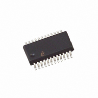
EL4511CU-T7 Intersil, EL4511CU-T7 Datasheet - Page 16

EL4511CU-T7
Manufacturer Part Number
EL4511CU-T7
Description
IC VID SYNC SEPARATR HDTV 24QSOP
Manufacturer
Intersil
Type
Synchronous Separatorr
Datasheet
1.EL4511CUZ.pdf
(24 pages)
Specifications of EL4511CU-T7
Applications
HDTV, Projectors, Set-Top Boxes
Mounting Type
Surface Mount
Package / Case
24-QSOP
Lead Free Status / RoHS Status
Contains lead / RoHS non-compliant
Timing Diagram 5 - 720p Standard with Filter in Circuit
Description of Operation
The EL4511 has 3 modes of operation. The first is default
mode with pins 1 and 24 connected to ground with 10K.
Second is using pins 1 and 24 to provide simple mode
control. The third is using the serial port to use a crystal or a
clock into XTALN pin 24 to determine the video sync rate
and/or more extensive mode control.
The EL4511 incorporates the following functional blocks:
• Analog I/Ps, processing, and slicing
• Signal source and polarity detector
• Signal & H rate acquisition block
• Advanced sync separator which will detect both
• Video lock and level indicators
• Reference counter
• Computer and control interface
Analog I/Ps, Processing, and Slicing
The EL4511 has three I/P pins which may be connected to a
source of external sync signals.
For YPrPb or RGB applications, Y or G should be connected
to SYNCIN. For applications with separate horizontal and
vertical sync inputs, these should be connected to HIN and
VERTIN, respectively. (HIN may also be used for composite
sync without video.)
Composite video input signals should be connected to
SYNCIN. This should be AC coupled from a low impedance
source. The input resistance is in the order of 100kΩ. After H
lock is obtained, this signal will be “soft clamped” (5kΩ) to
approximately 20% of the V
In the default mode, the clamping action ensures that the
correct slicing levels will be used throughout the field.
(Serial Mode) This operation can be modified through
Register 9. The soft clamp can be disabled by setting bit 3 to
conventional and tri-level sync signals
CCA1
16
voltage.
EL4511
Hi. Setting bit 1 to high will disconnect the input bias
network.
Once the acquisition process is complete (see below for
description), the slice level will be adaptive. The sync signal
is measured from sync tip to blanking level; (Tri-level is
measured between negative and positive sync tips). The
slice level is then set to 50% of these levels.
(Serial Mode) It is possible to force the slicing level to
remain at the fixed level of 78mV above the sync tip;
Register 2, bit 5 is set High to do this. This can help when
dealing with signal that have bursts of noise, or formats that
have signals that will modify the sync amplitude
measurement process.
VGA type of signals will be connected to the HIN and
VERTIN pins (use HIN for combined H & V). These are DC
coupled signals; they will be sliced at a fixed level of
approximately 1.4V. These inputs may be any combination
of positive and negative polarities; the EL4511 will invert as
required to keep the outputs in the correct polarity. (Serial
Mode) This polarity correction process may be modified with
Register 4 bits 3:0.
Signal and Horizontal Rate Acquisition Block
On power-up, if both HIN and SYNCIN are enabled; the
EL4511 will slice the SYNCIN input at 78mV above the
negative sync tip level and monitor the sliced signal for up to
320µs. If a periodic signal within the specified frequency
limits is found to be present, this is assumed to be the
horizontal frequency. If no signal is found, the EL4511 will
switch to slice and monitor the HIN input at a TTL level. The
EL4511 will continue to monitor these two signals in turn until
an appropriate signal is detected.
If only one of HIN and SYNCIN is enabled, the EL4511 will
continuously monitor the selected signal until an appropriate
signal is detected; this will give a shorter lock time where
only one type of signal is used. At this point, the rate
acquisition oscillator lock process (to the H rate signal) will
begin.
This waveform shows
the output jitter present
on the H
oscilloscope is triggered
from the positive
reference edge of the
composite sync output.
OUT
signal. The
November 12, 2010
FN7009.8


