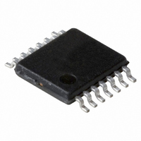
74LVT14DB,118 NXP Semiconductors, 74LVT14DB,118 Datasheet - Page 4

74LVT14DB,118
Manufacturer Part Number
74LVT14DB,118
Description
IC 3.3V HEX INV SCHM TRIG 14SSOP
Manufacturer
NXP Semiconductors
Series
74LVTr
Datasheet
1.74LVT14D118.pdf
(13 pages)
Specifications of 74LVT14DB,118
Logic Type
Inverter with Schmitt Trigger
Number Of Inputs
1
Number Of Circuits
6
Current - Output High, Low
20mA, 32mA
Voltage - Supply
2.7 V ~ 3.6 V
Operating Temperature
-40°C ~ 85°C
Mounting Type
Surface Mount
Package / Case
14-SSOP
Lead Free Status / RoHS Status
Lead free / RoHS Compliant
Other names
74LVT14DB-T
74LVT14DB-T
935209180118
74LVT14DB-T
935209180118
NXP Semiconductors
8. Recommended operating conditions
Table 5.
9. Static characteristics
Table 6.
At recommended operating conditions. Voltages are referenced to GND (ground = 0 V).
[1]
[2]
74LVT14_2
Product data sheet
Symbol
V
V
I
I
T
Symbol Parameter
V
V
V
V
V
V
V
V
I
I
I
C
OH
OL
I
OFF
CC
amb
t/ V
I
CC
I
T+
T
H
IK
IH
IL
OH
OL
I
CC
All typical values are measured at V
This is the increase in the supply current for each input at the specified voltage level other than V
positive-going threshold voltage
negative-going threshold voltage V
hysteresis voltage
input clamping voltage
HIGH-level input voltage
LOW-level input voltage
HIGH-level output voltage
LOW-level output voltage
input leakage current
power-off leakage current
supply current
additional supply current
input capacitance
Parameter
supply voltage
input voltage
HIGH-level output current
LOW-level output current
ambient temperature
input transition rise and fall rate
Recommended operating conditions
Static characteristics
CC
= 3.3 V (unless stated otherwise) and T
Conditions
V
V
V
V
V
V
V
V
V
V
V
V
V
per input pin; V
one input = V
other inputs at V
V
CC
CC
CC
CC
CC
CC
CC
CC
CC
CC
CC
CC
CC
CC
I
outputs HIGH
outputs LOW
= 0 V or 3.0 V
= 3.3 V; see
= 3.3 V; see
= 3.3 V; see
= 2.7 V; I
= 2.7 V to 3.6 V; I
= 2.7 V; I
= 3.0 V; I
= 2.7 V; I
= 2.7 V; I
= 3.0 V; I
= 0 V or 3.6 V; V
= 3.6 V; V
= 0 V; V
= 3.6 V; V
Conditions
in free air
output enabled
Rev. 02 — 25 April 2008
I
CC
IK
OH
OH
OL
OL
OL
or V
I
I
CC
= V
= GND or V
= –18 mA
= 100 A
= 24 mA
= 32 mA
CC
= 6 mA
= 20 mA
Figure 7
Figure 7
Figure 7
O
= 3.0 V to 3.6 V;
0.6 V
CC
or GND
= 0 V to 4.5 V
I
OH
= 5.5 V
or GND
= 100 A
CC
amb
; I
O
= 25 C.
= 0 A
Min
2.7
0
-
0
20
40
3.3 V hex inverter Schmitt trigger
[2]
CC
1.5
0.9
0.4
2.0
-
V
2.4
2.0
-
-
-
-
-
-
-
-
-
-
Typ
-
-
-
-
-
-
1.2
CC
or GND.
Min
40 C to +85 C
0.2 -
-
1.7
1.1
0.6
-
-
-
-
-
-
-
-
-
-
-
1.5
-
3
Typ
Max
3.6
5.5
-
32
+85
10
© NXP B.V. 2008. All rights reserved.
74LVT14
[1]
2.0
1.3
-
-
-
0.8
-
-
-
0.2
0.5
0.5
10
0.02
3
0.2
-
Max
1
100
Unit
V
V
mA
mA
ns/V
C
4 of 13
Unit
V
V
V
V
V
V
V
V
V
V
V
mA
mA
mA
pF
A
A
A


