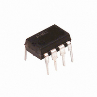
AT24C08B-PU Atmel, AT24C08B-PU Datasheet - Page 19

AT24C08B-PU
Manufacturer Part Number
AT24C08B-PU
Description
IC EEPROM 8KBIT 1MHZ 8DIP
Manufacturer
Atmel
Specifications of AT24C08B-PU
Format - Memory
EEPROMs - Serial
Memory Type
EEPROM
Memory Size
8K (1K x 8)
Speed
400kHz, 1MHz
Interface
I²C, 2-Wire Serial
Voltage - Supply
1.8 V ~ 5.5 V
Operating Temperature
-40°C ~ 85°C
Package / Case
8-DIP (0.300", 7.62mm)
Organization
1 K x 8
Interface Type
2-Wire
Maximum Clock Frequency
0.4 MHz
Access Time
900 ns
Supply Voltage (max)
5.5 V
Supply Voltage (min)
1.8 V
Maximum Operating Current
3 mA
Maximum Operating Temperature
+ 85 C
Mounting Style
Through Hole
Minimum Operating Temperature
- 40 C
Operating Supply Voltage
2.5 V, 3.3 V, 5 V
Memory Configuration
1024 X 8
Clock Frequency
1MHz
Supply Voltage Range
1.8V To 5.5V
Memory Case Style
DIP
No. Of Pins
8
Rohs Compliant
Yes
Lead Free Status / RoHS Status
Lead free / RoHS Compliant
Available stocks
Company
Part Number
Manufacturer
Quantity
Price
Company:
Part Number:
AT24C08B-PU
Manufacturer:
ATMEL
Quantity:
48
Part Number:
AT24C08B-PU
Manufacturer:
ATMEL/爱特梅尔
Quantity:
20 000
5TS1 – SOT23
5226A–SEEPR–06/07
NOTES: 1. This drawing is for general information only. Refer to JEDEC Drawing
R
2. Dimension D does not include mold flash, protrusions, or gate burrs.
3. The package top may be smaller than the package bottom. Dimensions
4. These dimensions apply to the flat section of the lead between 0.08 mm
5. Dimension "b" does not include Dambar protrusion. Allowable Dambar
1150 E. Cheyenne Mtn. Blvd.
Colorado Springs, CO 80906
MO-193, Variation AB, for additional information.
Mold flash, protrusions, or gate burrs shall not exceed 0.15 mm per end.
Dimension E1 does not include interlead flash or protrusion. Interlead
flash or protrusion shall not exceed 0.15 mm per side.
D and E1 are determined at the outermost extremes of the plastic body
exclusive of mold flash, tie bar burrs, gate burrs, and interlead flash, but
including any mismatch between the top and bottom of the plastic body.
and 0.15 mm from the lead tip.
protrusion shall be 0.08 mm total in excess of the "b" dimension at
maximum material condition. The Dambar cannot be located on the lower
radius of the foot. Minimum space between protrusion and an adjacent lead
shall not be less than 0.07 mm.
Seating
Plane
E1
1
5
Top View
b
Side View
TITLE
5TS1, 5-lead, 1.60 mm Body, Plastic Thin Shrink
Small Outline Package (SHRINK SOT)
e1
D
2
e
3
4
A2
E
A1
A
SYMBOL
A
A1
A2
c
D
E
E1
L1
e
e1
b
0.30
COMMON DIMENSIONS
0.00
0.70
0.08
MIN
(Unit of Measure = mm)
–
C
End View
2.90 BSC
2.80 BSC
1.60 BSC
0.60 REF
0.95 BSC
1.90 BSC
NOM
0.90
–
–
–
–
DRAWING NO.
C
PO5TS1
L
L1
MAX
1.10
0.10
1.00
0.20
0.50
NOTE
4, 5
2, 3
2, 3
2, 3
4
6/25/03
REV.
A
19


