CAT24AA16TDI-GT3 ON Semiconductor, CAT24AA16TDI-GT3 Datasheet
CAT24AA16TDI-GT3
Specifications of CAT24AA16TDI-GT3
Available stocks


Related parts for CAT24AA16TDI-GT3

CAT24AA16TDI-GT3 Summary of contents
Page 1
... Data is written by providing a starting address, then loading contiguous bytes into a Page Write Buffer, and then writing all data to non−volatile memory in one internal write cycle. Data is read by providing a starting address and then shifting out data serially while automatically incrementing the internal address count. ...
Page 2
Table 1. ABSOLUTE MAXIMUM RATINGS Parameters Storage Temperature Voltage on any Pin with Respect to Ground (Note 1) Stresses exceeding Maximum Ratings may damage the device. Maximum Ratings are stress ratings only. Functional operation above the Recommended Operating Conditions is ...
Page 3
Table 5. AC CHARACTERISTICS (Note 6) (V Symbol Parameter F Clock Frequency SCL t START Condition Hold Time HD:STA t Low Period of SCL Clock LOW t High Period of SCL Clock HIGH t START Condition Setup Time SU:STA t ...
Page 4
Power−On Reset (POR) Each CAT24AA16 incorporates Power−On Reset (POR) circuitry which protects the internal logic against powering up in the wrong state. The device will power up into Standby mode after V exceeds the POR trigger level and will CC ...
Page 5
... ACK will be returned and the host can then proceed with the next read or write operation. Hardware Write Protection With the WP pin held HIGH, the entire memory is protected against Write operations. If the WP pin is left floating or is grounded, it has no impact on the Write operation ...
Page 6
S BUS ACTIVITY MASTER T S SLAVE SCL th SDA 8 Bit Byte BUS ACTIVITY: A SLAVE R MASTER ADDRESS SLAVE ADDRESS BYTE ...
Page 7
... If, after receiving data sent by the Slave, the Master responds with ACK, then the Slave will continue transmitting until the Master responds with NoACK followed by STOP (Figure 12). During Sequential Read the internal byte address is automatically incremented up to the end of memory, where it then wraps around to the beginning of memory ...
Page 8
PIN # 1 IDENTIFICATION TOP VIEW SIDE VIEW Notes: (1) All dimensions are in millimeters. Angles in degrees. (2) Complies with JEDEC MS-012. PACKAGE DIMENSIONS SOIC 8, 150 mils CASE 751BD−01 ISSUE O SYMBOL ...
Page 9
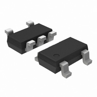
TOP VIEW SIDE VIEW Notes: (1) All dimensions are in millimeters. Angles in degrees. (2) Complies with JEDEC MO-193. PACKAGE DIMENSIONS TSOT−23, 5 LEAD CASE 419AE−01 ISSUE O SYMBOL MIN A A1 0.01 A2 ...
Page 10
... All packages are RoHS−compliant (Lead−free, Halogen−free). 10. The standard lead finish is NiPdAu. 11. The device used in the above example is a CAT24AA16TDI−GT3 (TSOT−23 5−Lead, Industrial Temperature, NiPdAu, Tape & Reel, 3,000/Reel). 12. The 10,000/Reel option is only available for the TSOT−23 5−Lead package. ...