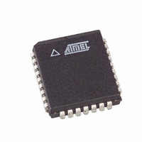
AT49LH004-33JX Atmel, AT49LH004-33JX Datasheet - Page 24

AT49LH004-33JX
Manufacturer Part Number
AT49LH004-33JX
Description
IC FLASH 4MBIT 33MHZ 32PLCC
Manufacturer
Atmel
Datasheet
1.AT49LH004-33JC.pdf
(40 pages)
Specifications of AT49LH004-33JX
Format - Memory
FLASH
Memory Type
FLASH
Memory Size
4M (512K x 8)
Speed
33MHz
Interface
Parallel
Voltage - Supply
3 V ~ 3.6 V
Operating Temperature
0°C ~ 85°C
Package / Case
32-PLCC
Lead Free Status / RoHS Status
Lead free / RoHS Compliant
Available stocks
Company
Part Number
Manufacturer
Quantity
Price
13.2
14. A/A Mux Interface
24
LPC Multiple Device Selection
AT49LH004
For LPC memory cycles, the inverse state of the strapping values on the ID[3:0] pins are com-
pared against address bits A22 - A19 to determine if the device should respond. If there is a
mismatch, the device will ignore the remainder of the cycle. The device will then enter standby
mode when the FWH4/LFRAME pin is high and no internal operation is in progress. The
FWH/LAD[3:0] pins will also be placed in a high-impedance state.
Table 13-2.
The A/A Mux interface is designed as a programming interface for OEMs to use during moth-
erboard manufacturing or component pre-programming. The term A/A Mux refers to the
multiplexed row and column addresses that this interface utilizes. The A/A Mux interface dra-
matically reduces the amount of overhead needed to access the device, allowing the device to
be tested and programmed quickly with automated test equipment (ATE) and PROM program-
mers in the OEM’s manufacturing flow. The number of signals required to use the interface
does not change with device density; therefore, the interface can accommodate larger density
devices while still allowing the device to fit into low lead-count packages.
Only basic read, erase, and program operations can be performed through the A/A Mux inter-
face; FWH/LPC features, such as the use of the Sector Locking Registers and the General-
purpose Input Register, are not available.
The A/A Mux interface mode is selected by driving the IC control pin high. The IC pin is inter-
nally pulled down in the device, so a modest amount of leakage current should be expected to
be drawn (see DC Specifications) when the pin is driven high.
0 (Boot Device)
Device
10
11
12
13
14
15
1
2
3
4
5
6
7
8
9
LPC Multiple Device Selection
ID3
0
0
0
0
0
0
0
0
1
1
1
1
1
1
1
1
ID2
ID Strapping Pins
0
0
0
0
1
1
1
1
0
0
0
0
1
1
1
1
ID1
0
0
1
1
0
0
1
1
0
0
1
1
0
0
1
1
ID0
0
1
0
1
0
1
0
1
0
1
0
1
0
1
0
1
3383D–FLASH–6/05
Address
A22-A19
1111b
1110b
1101b
1100b
1011b
1010b
1001b
1000b
0111b
0110b
0101b
0100b
0011b
0010b
0001b
0000b
Bits


