CY7C037V-15AC Cypress Semiconductor Corp, CY7C037V-15AC Datasheet
CY7C037V-15AC
Specifications of CY7C037V-15AC
Available stocks


Related parts for CY7C037V-15AC


CY7C037V-15AC Summary of contents
Page 1
... True Dual-Ported memory cells which allow simulta- neous access of the same memory location • 32K x 16 organization (CY7C027V) • 64K x 16 organization (CY7C028V) • 32K x 18 organization (CY7C037V) • 64K x 18 organization (CY7C038V) • 0.35-micron CMOS for optimum speed/power • High-speed access: 15/20/25 ns • ...
Page 2
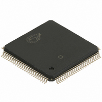
... An automatic power-down feature is controlled independently on each port by a chip select (CE) pin. The CY7C027V/028V and CY7037V/038V are available in 100-pin Thin Quad Plastic Flatpacks (TQFP). 100-Pin TQFP (Top View CY7C028V (64K x 16) CY7C027V (32K x 16 CY7C027V/028V CY7C037V/038V A9R 74 A10R 73 A11R 72 A12R 71 A13R 70 A14R 69 A15R [ LBR 65 UBR ...
Page 3
... Selection Guide Maximum Access Time (ns) Typical Operating Current (mA) Typical Standby Current for I (mA) (Both ports SB1 TTL level) Typical Standby Current for (Both ports SB3 CMOS level) Note: 6. This pin is NC for CY7C037V. 100-Pin TQFP (Top View CY7C038V (64K x 18) CY7C037V (32K x 18) ...
Page 4
... Ground No Connect [7] DC Input Voltage .................................. –0. Output Current into Outputs (LOW)............................. 20 mA Static Discharge Voltage .......................................... >1100V Latch-Up Current.................................................... >200 mA Operating Range Range Commercial +0.5V CC [8] Industrial – + CY7C027V/028V CY7C037V/038V V and –I/O for x18 –I/O for x18 devices –I/O for x18 devices) ...
Page 5
... Com’l. 75 105 [9] [8] Ind. Test Conditions MHz 3. 250 TH OUTPUT (b) Thévenin Equivalent (Load 1) ALL INPUT PULSES 3.0V 90% 90% 10% GND CY7C027V/028V CY7C037V/038V CY7C027V/028V CY7C037V/038V -20 -25 Min. Typ. Max. Min. Typ. 2.4 2.4 0.4 2.2 2.2 0 –10 10 –10 120 175 115 140 195 ...
Page 6
... For information on port-to-port delay through RAM cells from writing port to reading port, refer to Read Timing with Busy waveform. 17. Test conditions used are Load 1. 18 calculated parameter and is the greater of t BDD [11] -15 Min. Max less than t and t HZCE LZCE HZOE –t (actual –t (actual). WDD PWE DDD SD 6 CY7C027V/028V CY7C037V/038V CY7C027V/028V CY7C037V/038V -20 -25 Min. Max. Min. Max ...
Page 7
... The RAM can begin operation >t RC minimum operating voltage (3.0 volts). [11] (continued) -15 Min. Max Timing after V reaches the CC Parameter ICC DR1 Note: 19 tested. 7 CY7C027V/028V CY7C037V/038V CY7C027V/028V CY7C037V/038V -20 -25 Min. Max. Min. Max Data Retention Mode 3.0V 3. – 0. [19] Test Conditions Max ...
Page 8
... Address valid prior to or coincident with CE transition LOW. 24. To access RAM SEM = [20, 21, 22 [20, 23, 24] t ACE t DOE t LZOE t LZCE LZCE t ABE t ACE t LZCE . This waveform cannot be used for semaphore reads access semaphore SEM = CY7C027V/028V CY7C037V/038V t OHA DATA VALID t HZCE t HZOE DATA VALID OHA t HZCE t HZCE ...
Page 9
... If the CE or SEM LOW transition occurs simultaneously with or after the R/W LOW transition, the outputs remain in the high-impedance state. [25, 26, 27, 28 [28] t PWE [31] t HZWE t SD [25, 26, 27, 33 SCE LOW CE or SEM and a LOW UB or LB. PWE or (t PWE HZWE . CY7C027V/028V CY7C037V/038V [31] t HZOE LZWE NOTE allow the I/O drivers to turn off and data to be placed PWE ...
Page 10
... SPS [34 SCE SOP t SD DATA VALID PWE t SWRD t SOP WRITE CYCLE READ CYCLE [35, 36, 37] MATCH t SPS MATCH = CE = HIGH CY7C027V/028V CY7C037V/038V t t SAA OHA VALID ADRESS t ACE DATA VALID OUT t DOE ...
Page 11
... Switching Waveforms (continued) Timing Diagram of Read with BUSY (M/S=HIGH) ADDRESS R R/W R DATA ADDRESS L BUSY L DATA OUTL Write Timing with Busy Input (M/S=LOW) R/W BUSY Note: 38 LOW [38 MATCH t PWE t SD VALID MATCH t BLA t PWE CY7C027V/028V CY7C037V/038V BHA t BDD t DDD VALID t WDD ...
Page 12
... Note: 39 violated, the busy signal will be asserted on one side or the other, but there is no guarantee to which side BUSY will be asserted. PS [39] ADDRESS MATCH BLC ADDRESS MATCH BLC [39 ADDRESS MISMATCH t t BLA BHA ADDRESS MISMATCH t t BLA BHA 12 CY7C027V/028V CY7C037V/038V t BHC t BHC ...
Page 13
... Left Side Clears INT : L ADDRESS R INT L Notes: 40. t depends on which enable pin ( depends on which enable pin (CE INS INR [40 (FFFF for CY7C028V/38V) [41] t INR t WC [40 (FFFF for CY7C028V/38V) [41] t INR ) is deasserted first R asserted last CY7C027V/028V CY7C037V/038V t RC READ 7FFF t RC READ 7FFE ...
Page 14
... If both ports attempt to ac- cess the semaphore within t definitely be obtained by one side or the other, but there is no guaran- tee which side will control the semaphore. 14 CY7C027V/028V CY7C037V/038V of each other, the busy logic will determine PS is violated, one port will definitely gain PS after an address match ...
Page 15
... Right port has semaphore token 1 1 Semaphore free 0 1 Left port has semaphore token 1 1 Semaphore free 15 CY7C027V/028V CY7C037V/038V I/O –I/O Operation 0 8 Deselected: Power-Down Deselected: Power-Down Write to Upper Byte Only Write to Lower Byte Only Write to Both Bytes Read Upper Byte Only ...
Page 16
... Asynchronous Dual-Port SRAM Speed (ns) Ordering Code 15 CY7C028V-15AC 20 CY7C028V-20AC CY7C028V-20AI 25 CY7C028V-25AC 32K x18 3.3V Asynchronous Dual-Port SRAM Speed (ns) Ordering Code 15 CY7C037V-15AC 20 CY7C037V-20AC 25 CY7C037V-25AC 64K x18 3.3V Asynchronous Dual-Port SRAM Speed (ns) Ordering Code 15 CY7C038V-15AC 20 CY7C038V-20AC CY7C038V-20AI 25 CY7C038V-25AC Document #: 38–00670–*D ...
Page 17
... The inclusion of Cypress Semiconductor products in life-support systems application implies that the manufacturer assumes all risk of such use and in doing so indemnifies Cypress Semiconductor against all charges. CY7C027V/028V CY7C037V/038V ...