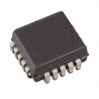
AT17LV512-10JU Atmel, AT17LV512-10JU Datasheet - Page 9

AT17LV512-10JU
Manufacturer Part Number
AT17LV512-10JU
Description
IC SRL CONFG EEPROM 512K 20-PLCC
Manufacturer
Atmel
Datasheet
1.AT17LV65-10CC.pdf
(26 pages)
Specifications of AT17LV512-10JU
Programmable Type
Serial EEPROM
Memory Size
512kb
Voltage - Supply
3 V ~ 3.6 V, 4.5 V ~ 5.5 V
Operating Temperature
-40°C ~ 85°C
Package / Case
20-LCC (J-Lead)
Organization
512 Kbit x 1
Interface Type
2-Wire
Maximum Clock Frequency
15 MHz
Access Time
25 ns
Supply Voltage (max)
7 V
Supply Voltage (min)
- 0.5 V
Maximum Operating Current
10 mA
Maximum Operating Temperature
+ 85 C
Mounting Style
SMD/SMT
Minimum Operating Temperature
- 40 C
Operating Supply Voltage
3.3 V, 5 V
For Use With
ATDH2225 - CABLE ISP FOR AT17ATDH2200E - CONFIGURATOR PROGRAM BOARD KIT
Lead Free Status / RoHS Status
Lead free / RoHS Compliant
Available stocks
Company
Part Number
Manufacturer
Quantity
Price
Company:
Part Number:
AT17LV512-10JU
Manufacturer:
Atmel
Quantity:
135
Part Number:
AT17LV512-10JU
Manufacturer:
ATMEL/爱特梅尔
Quantity:
20 000
7. Cascading Serial Configuration EEPROMs
8. AT17LV Series Reset Polarity
9. Programming Mode
10. Standby Mode
2321I–CNFG–2/08
For multiple FPGAs configured as a daisy-chain, or for FPGAs requiring larger configuration
memories, cascaded configurators provide additional memory.
After the last bit from the first configurator is read, the clock signal to the configurator asserts its
CEO output Low and disables its DATA line driver. The second configurator recognizes the Low
level on its CE input and enables its DATA output.
After configuration is complete, the address counters of all cascaded configurators are reset if
the RESET/OE on each configurator is driven to its active (Low) level.
If the address counters are not to be reset upon completion, then the RESET/OE input can be
tied to its inactive (High) level.
The AT17LV65 devices do not have the CEO feature to perform cascaded configurations.
The AT17LV series configurator allows the user to program the reset polarity as either
RESET/OE or RESET/OE. This feature is supported by industry-standard programmer
algorithms.
The programming mode is entered by bringing SER_EN Low. In this mode the chip can be pro-
grammed by the Two-Wire serial bus. The programming is done at V
Programming super voltages are generated inside the chip.
The AT17LV series configurators enter a low-power standby mode whenever CE is asserted
High. In this mode, the AT17LV65/128/256 configurator consumes less than 50 µA of current at
3.3V (100 µA for the AT17LV512/010 and 200 µA for the AT17LV002/040). The output remains
in a high-impedance state regardless of the state of the OE input.
AT17LV65/128/256/512/010/002/040
CC
supply only.
9


