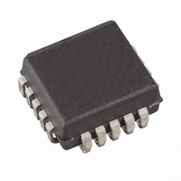
AT17C128A-10JC Atmel, AT17C128A-10JC Datasheet

AT17C128A-10JC
Specifications of AT17C128A-10JC
Available stocks
Related parts for AT17C128A-10JC
AT17C128A-10JC Summary of contents
Page 1
... The AT17A Series Configurators can be programmed with industry-standard program- mers or Atmel’s ATDH2200E Programming Kit. Pin Configurations 20-lead PLCC DCLK (WP ® Devices SER_EN FPGA Configuration EEPROM Memory 64-kilobit, 128-kilobit and 256-kilobit Altera Pinout AT17C65A AT17LV65A AT17C128A AT17LV128A AT17C256A AT17LV256A Rev. 0996D–08/01 1 ...
Page 2
Block Diagram POWER ON RESET Device Configuration AT17C/LV65A/128A/256A 2 The control signals for the configuration EEPROM – nCS, OE, and DCLK – interface directly with the FPGA device control signals. All FPGA devices can control the entire configuration process and ...
Page 3
FPGA Device Configuration 0996D–08/01 This document discusses the EPF8K and EPF10K device interfaces. For more details or information on other Altera applications, please reference the “AT17A Series Conver- sions from Altera FPGA Serial Configuration Memories” application note. FPGA devices can ...
Page 4
Figure 1. FPGA Device Configured with a Single AT17A Series Configurator EPF6K m nCONFIG 0.1 F CONF_DONE GND nS/P MSEL0 GND Notes: 1. Reset polarity must be set active Low filter recommended for ...
Page 5
... The programming is done at V Programming super voltages are generated inside the chip. See the “Programming Specification for Atmel’s Configuration EEPROM” application note for further informa- tion. The AT17CXXXA parts are read/write at 5V nominal. The AT17LVXXXA parts are read/write at 3 ...
Page 6
... OE is High. It will then follow nCS until OE goes Low, thereafter, nCASC will stay High until the entire EEPROM is read again Device selection input, A2. This is used to enable (or select) the device during programming (i.e., when SER_EN is Low; please refer to the “Programming Specification for Atmel’s Configuration EEPROM” application note for more details). 18 SER_EN I Serial enable must be held High during FPGA loading operations ...
Page 7
Absolute Maximum Ratings* Operating Temperature.................................. -55°C to +125°C Storage Temperature ..................................... -65 °C to +150°C Voltage on Any Pin with Respect to Ground ............................. -0. Supply Voltage (V ) .........................................-0.5V to +7.0V CC Maximum Soldering Temp. (10 sec. ...
Page 8
DC Characteristics ± 5% Commercial; 5V ± 10% Industrial/Military CC Symbol Description V High-level Input Voltage IH V Low-level Input Voltage IL V High-level Output Voltage ( Low-level Output Voltage ( High-level Output ...
Page 9
AC Characteristics nCS T SCE OE DCLK DATA AC Characteristics when Cascading OE nCS DCLK T CDF LAST BIT DATA T OCK CEO 0996D–08/01 AT17C/LV65A/128A/256A CAC OH T OCE T ...
Page 10
... Maximum Input Clock Frequency MAX Notes: 1. Preliminary specifications for military operating range only test load = 50 pF. 3. Float delays are measured with loads. Transition is measured ± 200 mV from steady-state active levels. AC Characteristics for AT17C128A when Cascading ± 5% Commercial ± 10% Industrial/Military CC CC Symbol ...
Page 11
AC Characteristics for AT17C256A ± 5% Commercial ± 10% Industrial/Military CC CC Symbol Description ( Data Delay OE (2) T nCS to Data Delay CE (2) T DCLK to Data Delay ...
Page 12
AC Characteristics for AT17LV65A/128A/256A V = 3.3V ± 10% CC Symbol Description ( Data Delay OE (2) T nCS to Data Delay CE (2) T DCLK to Data Delay CAC T Data Hold from nCS ...
Page 13
... Ordering Information – 5V Devices Memory Size Ordering Code (2) 64-Kbit AT17C65A-10JC AT17C65A-10JI 128-Kbit AT17C128A-10JC AT17C128A-10JI (3) 256-Kbit AT17C256A-10JC AT17C256A-10JI Notes: 1. Currently, there are two types of low-density configurators. The new version will be identified by a “B” after the datacode. The “B” version is fully backward-compatible with the original devices so existing customers will not be affected. The new parts no longer require a MUX for ISP ...
Page 14
Packaging Information 20J, 20-lead, Plastic J-leaded Chip Carrier (PLCC) Dimensions in Inches and (Millimeters) JEDEC STANDARD MS-018 AA AT17C/LV65A/128A/256A 14 0996D–08/01 ...
Page 15
... No licenses to patents or other intellectual property of Atmel are granted by the Company in connection with the sale of Atmel products, expressly or by implication. Atmel’s products are not authorized for use as critical components in life support devices or systems. ...


