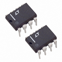
LT1512CN8#PBF Linear Technology, LT1512CN8#PBF Datasheet - Page 10

LT1512CN8#PBF
Manufacturer Part Number
LT1512CN8#PBF
Description
IC BATT CHRGR CONST I/V 8-DIP
Manufacturer
Linear Technology
Datasheet
1.LT1512CN8PBF.pdf
(12 pages)
Specifications of LT1512CN8#PBF
Function
Charge Management
Battery Type
All Battery Types
Voltage - Supply
2.7 V ~ 25 V
Operating Temperature
0°C ~ 70°C
Mounting Type
Through Hole
Package / Case
8-DIP (0.300", 7.62mm)
Lead Free Status / RoHS Status
Lead free / RoHS Compliant
Available stocks
Company
Part Number
Manufacturer
Quantity
Price
LT1512
APPLICATIONS INFORMATION
input to R5 is equal to the processor V
by the inverse PWM ratio. This assumes that the PWM
signal is a CMOS output that swings rail-to-rail with a
source resistance less than a few hundred ohms. The
negative voltage is converted to a current by R5 and R6
and fi ltered by C7. This current multiplied by R4 generates
a voltage that subtracts from the 100mV sense voltage
of the LT1512. This is not a high precision technique
because of the errors in V
it can typically be used to adjust charging current over a
20% to 100% range with good repeatability (full charg-
ing current accuracy is not affected). To reduce the load
on the logic signal, R4 has been increased from 24Ω to
200Ω. This causes a known increase in full-scale charging
PACKAGE DESCRIPTION
10
NOTE:
1. DIMENSIONS ARE
*THESE DIMENSIONS DO NOT INCLUDE MOLD FLASH OR PROTRUSIONS.
MOLD FLASH OR PROTRUSIONS SHALL NOT EXCEED .010 INCH (0.254mm)
(7.620 – 8.255)
(0.203 – 0.381)
8.255
.008 – .015
.300 – .325
.325
CC
+.035
–.015
+0.889
–0.381
and the diode voltage, but
MILLIMETERS
INCHES
CC
level multiplied
Dimensions in inches (millimeters) unless otherwise noted.
8-Lead PDIP (Narrow 0.300)
(LTC DWG # 05-08-1510)
(1.651)
(6.477 0.381)
.065
TYP
.255 .015*
N8 Package
(2.54)
current (PWM = 0) of 3% due to the 5k input resistance of
the I
current and that very low duty cycles (especially zero!)
will not operate correctly. Very low duty cycle (<10%)
is a problem because the peak detector requires a fi nite
up-time to reset C6.
More Help
Linear Technology Field Application Engineers have a CAD
spreadsheet program for detailed calculations of circuit
operating conditions, and our Applications Department is
always ready to lend a helping hand. For additional informa-
tion refer to the LT1372 data sheet. This part is identical to
the LT1512 except for the current amplifi er circuitry.
.100
BSC
(1.143 – 1.651)
.045 – .065
FB
8
1
pin. Note that 100% duty cycle gives full charging
2
7
(10.160)
MAX
.400*
6
3
4
5
(0.457 0.076)
.018 .003
(3.302 0.127)
.130 .005
(3.048)
.120
MIN
(0.508)
.020
MIN
N8 1002
1512fa


