ISL6297CRZ-T Intersil, ISL6297CRZ-T Datasheet
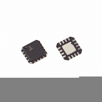
IC CHARGER LI-ION POLYMER 16-QFN

ISL6297CRZ-T

Manufacturer Part Number
ISL6297CRZ-T
Description
IC CHARGER LI-ION POLYMER 16-QFN
Manufacturer
Intersil
Datasheet

Specifications of ISL6297CRZ-T

Function
Charge Management
Battery Type
Lithium-Ion (Li-Ion), Lithium-Polymer (Li-Pol)
Voltage - Supply
4.3 V ~ 6.5 V
Operating Temperature
-20°C ~ 70°C
Mounting Type
Surface Mount
Package / Case
16-VQFN Exposed Pad, 16-HVQFN, 16-SQFN, 16-DHVQFN
Lead Free Status / RoHS Status
Lead free / RoHS Compliant
Other names
ISL6297CRZ-TTR
Li-ion/Li Polymer Battery Charger
The ISL6297 is a Dual-Mode Lithium Ion battery charger
optimized for cellular phone travel charger applications. It
uses Intersil’s patent-pending dual-mode charge
technology to minimize the heat normally generated in a
linear charger. By minimizing the heat generation, the
ISL6297 can be placed inside the connector of the travel
charger to completely remove the influence of the adapter
cable on the charging performance.
The ISL6297 is an enhancement of the original ISL6292B.
New features include improved accuracy, pre-charge circuit
verification, and enhanced LED indicator function.
Working with a current-limited AC/DC converter, the dual-
mode charger charges a Li-ion battery with the same current
profile as a traditional linear charger. The constant charge
current is determined by the current limit of the AC/DC
converter. The constant output voltage is fixed at 4.2V. When
the battery voltage is below 2.8V, the charger preconditions
the battery with a low trickle-charge current. The charge
status is indicated by a bi-color LED. A safety timer prevents
charging a dead battery for an excessively long period.
The ISL6297 also features THERMAGUARD™, a thermal
foldback function that automatically reduces the charge
current when the internal die temperature exceeds a +100°C
limit to prevent further temperature rise. This function
removes the concern of thermal failure in the targeted
space-limited applications. An ambient temperature
monitoring circuit allows users to set two separate
temperature limit levels, for charge and non-charge
conditions. The thermally-enhanced QFN package further
improves the thermal performance of the ISL6297 in space-
limited applications.
Pinout
TIME
GRN
RED
VIN
1
2
3
4
16
5
(16 LD QFN)
TOP VIEW
ISL6297
®
15
6
1
14
7
13
8
Data Sheet
12
11
10
9
VSEN
TEMP
IMIN
IREF
Thermaguard is a trademark of Intersil Americas Inc. Copyright Intersil Americas Inc. 2005-2006, 2007. All Rights Reserved
1-888-INTERSIL or 1-888-468-3774
CAUTION: These devices are sensitive to electrostatic discharge; follow proper IC Handling Procedures.
Features
• Complete Charger for Single-Cell Li-ion Batteries
• Integrated Pass Element and Current Sensor
• No External Blocking Diode Required
• Very Low Thermal Dual-Mode Operation
• 0.7% Voltage Accuracy with Remote Sense
• Pre-charge circuit verification with LED status indication
• Drives a bi-color LED
• Programmable Safety Timer
• Programmable Current Limit up to 1.5A
• Programmable End-of-Charge Current
• THERMAGUARD™ Charge Current Thermal Foldback
• NTC Thermistor Interface for Battery Temperature Monitor
• Two-Level Ambient Temperature Setting
• Guaranteed to Operate at 2.65V After Start-Up
• Ambient Temperature Range: -20°C to +70°C
• Thermally-Enhanced QFN Packages
• QFN Package:
• Pb-Free Plus Anneal Available (RoHS Compliant)
Applications
• PDAs, Cell Phones and Smart Phones
• Portable Instruments, MP3 Players
• Medical Handhelds
• Self-Charging Battery Packs
• Stand-Alone Chargers
Ordering Information
ISL6297CR*
ISL6297CRZ*
(Note)
*Add “-T” suffix for tape and reel. Please refer to TB347 for details on
reel specifications.
NOTE: Intersil Pb-free plus anneal products employ special Pb-free
material sets; molding compounds/die attach materials and 100%
matte tin plate termination finish, which are RoHS compliant and
compatible with both SnPb and Pb-free soldering operations. Intersil
Pb-free products are MSL classified at Pb-free peak reflow
temperatures that meet or exceed the Pb-free requirements of
IPC/JEDEC J STD-020.
- Compliant to JEDEC PUB95 MO-220
- Near Chip Scale Package footprint, which improves
NUMBER
QFN - Quad Flat No Leads - Package Outline
PCB efficiency and has a thinner profile
PART
All other trademarks mentioned are the property of their respective owners.
July 30, 2007
|
Intersil (and design) is a registered trademark of Intersil Americas Inc.
ISL 6297CR
62 97CRZ
MARKING
PART
RANGE (°C)
-20 to +70
-20 to +70
TEMP.
16 Ld 4x4 QFN L16.4x4
16 Ld 4x4 QFN
(Pb-free)
PACKAGE
ISL6297
FN9215.2
L16.4x4
DWG. #
PKG.

Related parts for ISL6297CRZ-T

ISL6297CRZ-T Summary of contents

Page 1

... Portable Instruments, MP3 Players • Medical Handhelds • Self-Charging Battery Packs • Stand-Alone Chargers Ordering Information PART NUMBER ISL6297CR* 12 VSEN ISL6297CRZ* (Note) 11 TEMP *Add “-T” suffix for tape and reel. Please refer to TB347 for details on 10 IMIN reel specifications. 9 IREF NOTE: Intersil Pb-free plus anneal products employ special Pb-free material sets ...

Page 2

... QFN Package . . . . . . . . . . . . . . . . Junction Temperature Range . . . . . . . . . . . . . . . . .-55°C to +150°C Operating Temperature Range . . . . . . . . . . . . . . . . .-40°C to +85°C Storage Temperature Range . . . . . . . . . . . . . . . . . .-65°C to +150°C Pb-free reflow profile . . . . . . . . . . . . . . . . . . . . . . . . . .see link below http://www.intersil.com/pbfree/Pb-FreeReflow.asp = 5V and +25°C ambient temperature. Maximum and minimum values are IN SYMBOL TEST CONDITIONS ...

Page 3

Electrical Specifications Typical values are tested at V guaranteed over recommended operating conditions, unless otherwise noted. (Continued) PARAMETER BATTERY TEMPERATURE MONITORING Low Temperature Threshold Low Temperature Hysteresis High Temperature Threshold High Temperature Hysteresis DT Pin MOSFET On Resistance Charge Current ...

Page 4

Pin Description PIN # PIN NAME 1, 15, 16 VIN VIN is the input power source recommended to have a 1Ω resistor in series with the input decoupling capacitor to prevent an over-shoot voltage when the input cable ...

Page 5

Block Diagram VIN Temperature TEMPERATURE C 1 Monitoring MONITORING IREF R IREF CURRENT Current REFERENCES References IMIN I MIN R IMIN I SEN V2P9 TEMP NTC NTC INTERFACE Interface DT TIME GND 5 ISL6297 Q MAIN ...

Page 6

State Diagram POR TEMP FAULT CLEARED (RETURN TO PREVIOUS STATE) TEMPERATURE FAULT LED: YELLOW CHARGER: OFF ANY TEMP FAULT RECHARGE LED: GREEN TIMEOUT AND CHARGER > 4.05V AND SEN I < I CHG MIN TIMER RESTART ...

Page 7

... Theory of Operation The ISL6297 is based on the Intersil Patent-pending dual- mode charging technology. This allows the ISL6297 to function as a traditional linear charger when powered with a voltage-source adapter. However, when powered with a current-limited adapter, the charger minimizes the thermal dissipation commonly seen in traditional linear chargers. ...

Page 8

... ISL6297 battery. More information can be found in the ISL6292 Constant Inhibit datasheet available at http://www.intersil.com. Functional Overview BATTERY VOLTAGE Battery Voltage After applying power to the ISL6297, but before charging starts, the ISL6297 gives a “Plug-in indication” by sequencially turning on a red, a green and a yellow indicator ...

Page 9

V2P9 pin outputs 2.9V, the open-drain MOSFET on the DT pin is turned on, and the ambient temperature monitoring circuit starts to function. EN Pin If all other charge conditions are met, pulling the ...

Page 10

VIN V2P9 500ms DT RED GRN OFF RED LEDS EN VSEN I CHG 500ms EN Battery connected here, but voltage remains above the battery detect (falling) threshold V IN 4.4V VSEN I CHG Charge terminates POR required before ...

Page 11

POR THRESHOLD V IN V2P9 EN DT IMPEDANCE RED GRN V SEN I CHG Internal Oscillator The internal oscillator establishes a timing reference. The oscillation period is programmable with an external timing capacitor shown in “Typical Application” ...

Page 12

During a recharge operation, the indicator remains green. When a temperature fault happens, both the RED and the GRN pins turn on to indicate a yellow color. This fault is ...

Page 13

When the charger starts to charge turned off to set a higher temperature range determined by the external resistor R . The equivalent circuit is shown in Figure 10B. ...

Page 14

The ratio the TEMP pin voltage to the bias voltage is --------------------- - and K × R ------------ - – ...

Page 15

Hysteresis Temperature Calculation Re-arranging Equation 8, and including the effect of R gives: K × R ------------ - – – Using the K/(1-K) ratio at the hysteresis threshold, Equation 18 provides the ...

Page 16

... Accordingly, the reader is cautioned to verify that data sheets are current before placing orders. Information furnished by Intersil is believed to be accurate and reliable. However, no responsibility is assumed by Intersil or its subsidiaries for its use; nor for any infringements of patents or other rights of third parties which may result from its use ...

Related keywords