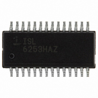
ISL6253HAZ Intersil, ISL6253HAZ Datasheet - Page 15

ISL6253HAZ
Manufacturer Part Number
ISL6253HAZ
Description
IC CTRLR BATTERY CHARGER 28QSOP
Manufacturer
Intersil
Datasheet
1.ISL6253HAZ.pdf
(22 pages)
Specifications of ISL6253HAZ
Function
Charge Management
Battery Type
Lithium-Ion (Li-Ion), Lithium-Polymer (Li-Pol)
Voltage - Supply
7 V ~ 25 V
Operating Temperature
-10°C ~ 100°C
Mounting Type
Surface Mount
Package / Case
28-SSOP (0.150", 3.95mm Width)
Rohs Compliant
YES
Lead Free Status / RoHS Status
Lead free / RoHS Compliant
Available stocks
Company
Part Number
Manufacturer
Quantity
Price
Company:
Part Number:
ISL6253HAZ
Manufacturer:
Intersil
Quantity:
75
Company:
Part Number:
ISL6253HAZ-T
Manufacturer:
Intersil
Quantity:
1 600
DC Adapter Detection
Connect the DC adapter voltage like aircraft power through a
resistor divider to DCSET to detect when DC power is
available, as shown in Figure 18. DCPRN is an open-drain
output and is high impedance when DCSET is less than
V
V
Where I
V
hysteresis is I
and 4.8µA (max.)
Current Measurement
Use ICM to monitor the input current being sensed across
CSIP and CSIN. The output voltage range is 0 to 2.5V. The
voltage of ICM is proportional to the voltage drop across
CSIP and CSIN, and is given by the following equation:
where I
ICM has ±5% accuracy. Connect a low pass filter to ICM to
bypass the switching frequency noise.
LDO Regulator
VDD provides a 5.0V supply voltage from the internal LDO
regulator from DCIN and can deliver up to 30mA of current.
This 30mA current is only used to supply the analog and
logic circuits for the IC and power the gate drivers. The
MOSFET drivers are powered by VDDP, and VDDP
connects to VDD through an external low pass filter. Bypass
VDDP and VDD with a 1µF capacitor.
Supply Isolation
If the voltage across the adapter sense resistor R2 is
typically greater than 8.5mV, the p-channel MOSFET
controlled by SGATE is turned on reducing the power
dissipation. If the voltage across the adapter sense resistor
R2 is less than 2mV, SGATE turns off the p-channel
MOSFET isolating the adapter from the system bus.
Battery Power Source Selection and Aircraft
Power Application
The battery voltage is monitored by CSON. If the battery
voltage measured on CSON is less than the adapter voltage
measured on DCIN, then the p-channel MOSFET controlled
by BGATE turns off. If it is greater, then BGATE turns on the
battery discharge p-channel MOSFET to minimize the power
loss. In the meantime, it also disables charging function and
turns off the AC adapter isolation p-channel MOSFET
controlled by SGATE. If designing for airplane power,
ICM
V
V
ACSET
th,rise
th,fall
th fall
th rise
,
,
=
. V
19.22
, and active low impedance when DCSET is above
INPUT
hys
= 1.235V (min), 1.26V (typ.) and 1.285V (max.). The
=
th,rise
=
is the DCSET input bias current hysteresis and
R
--------- -
R
•
R
--------- -
R
13
14
hys
I
is the DC current drawn from the AC adapter.
13
14
INPUT
and V
+
+
R
1
1
13
•
, where I
•
•
th,fall
V
V
R
DCSET
DCSET
2
are given by:
15
hys
–
I
hys
= 2µA (min.), 3.4µA (typ.)
R
13
(EQ. 6)
(EQ. 7)
ISL6253
DCSET is tied to a resistor divider sensing the adapter
voltage. When a user is plugged into the 15V airplane supply
and their battery is lower than 15V, the MOSFET driven by
BGATE (see Figure 18) is turned off and keeps the battery
from supplying the system bus. The comparator looking at
CSON and DCIN has 300mV of hysteresis to avoid
chattering. For aircraft power applications the ISL6253 is
only able to support 2S and 3S battery packs when disabling
the charging function based on DCPRN and ACPRN signals.
For 4S battery packs, DCSET = 0 and the DCPRN signal is
not available to support aircraft power applications.
Short Circuit Protection and 0V Battery Charging
Since the battery charger will regulate the charge current to
be trickle charge current, as long as the battery voltage is
below 3.0V/cell, it automatically has short circuit protection
and is able to provide the trickle charge current and “wake-
up” an extremely discharged battery.
Over Temperature Protection
If the die temp exceeds 150°C, it stops charging. Once the
die temp drops below 130°C, charging will start up again.
Application Information
The following battery charger design refers to the typical
application circuit in Figure 17, where a typical battery
configuration of 4S2P is used. This section describes how to
select the external components including the inductor, input
and output capacitors, switching MOSFETs, and current
sensing resistors.
Inductor Selection
The inductor selection has trade-offs between cost, size and
efficiency. For example, the lower the inductance, the
smaller the size, but ripple current is higher. This also results
in higher ac losses in the magnetic core and the windings,
which decrease the system efficiency. On the other hand,
the higher inductance results in lower ripple current and
smaller output filter capacitors, but it has higher DCR (dc
resistance of the inductor) loss, and has slower transient
response. So, the practical inductor design is based on the
inductor ripple current being ±(15-20)% of the maximum
operating dc current at maximum input voltage. The required
inductance can be calculated from:
where V
voltage, battery voltage and switching frequency,
respectively. The inductor ripple current ∆I
where the maximum peak-to-peak ripple current is 30% of
the maximum charge current used.
L
∆
I
L
=
=
V
-------------------------------------------- -
30%
IN MAX
,
IN,MAX
⋅
∆
I
BAT MAX
I
L
–
V
, V
,
BAT
BAT
----------------------------
V
, and f
IN MAX
V
,
BAT
s
f
s
are the maximum input
L
is found from:
(EQ. 8)
(EQ. 9)


