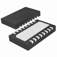
LTC3550EDHC#PBF Linear Technology, LTC3550EDHC#PBF Datasheet - Page 15

LTC3550EDHC#PBF
Manufacturer Part Number
LTC3550EDHC#PBF
Description
IC CHARGER BATT DUAL 16-DFN
Manufacturer
Linear Technology
Datasheet
1.LTC3550EDHCPBF.pdf
(24 pages)
Specifications of LTC3550EDHC#PBF
Function
Charge Management
Battery Type
Lithium-Ion (Li-Ion)
Voltage - Supply
4.3 V ~ 8 V
Operating Temperature
-40°C ~ 85°C
Mounting Type
Surface Mount
Package / Case
16-WFDFN Exposed Pad
Lead Free Status / RoHS Status
Lead free / RoHS Compliant
Available stocks
Company
Part Number
Manufacturer
Quantity
Price
Figure 2 shows the basic LTC3550 application circuit.
External component selection is driven by the charging
requirements and the buck regulator load requirements.
Programming and Monitoring Charge Current
The charge current delivered to the battery from the wall
adapter supply is programmed using a single resistor from
the IDC pin to ground.
Similarly, the charge current from the USB supply is
programmed using a single resistor from the IUSB pin
to ground. Setting HPWR pin to its high state will select
100% of the programmed charge current, while setting
HPWR to its low state will select 20% of the programmed
charge current.
APPLICATIO S I FOR ATIO
ADAPTER
WALL
PORT
R
R
I
I
CHRG USB
CHRG USB
USB
IDC
IUSB
=
(
(
C2
=
I
C1
CHRG DC
I
1000
CHRG USB
)
)
1000
= =
=
Figure 2. LTC3550 Basic Circuit
(
R
1000
200
R
R
(
V
IUSB
IUS
IUSB
V
)
U
R
,
V
B B
IDC
)
I
V
CHRG DC
(
(
HPWR HIGH
HPWR LOW
USBIN
IUSB
IDC
DCIN
(
HPWR HIGH
U
LTC3550
(
GND
ITERM
)
RUN
BAT
=
=
V
V
=
SW
CC
FB
=
1000
R
W
C
IDC
F
R
L1
ITERM
)
C
)
V
IN
)
R2
R1
+
U
3550 F02
4.2V
SINGLE
CELL Li-Ion
BATTERY
C
V
1.2V
600mA
OUT
OUT
Charge current out of the BAT pin can be determined at
any time by monitoring the IDC or IUSB pin voltage and
using the following equations:
Programming Charge Termination
The charge cycle terminates when the charge current falls
below the programmed termination threshold during con-
stant-voltage mode. This threshold is set by connecting an
external resistor, R
The charge termination current threshold (I
set by the following equation:
The termination condition is detected by using an internal
fi ltered comparator to monitor the ITERM pin. When the
ITERM pin voltage drops below 100mV* for longer than
t
charge current is latched off and the LTC3550 enters
standby mode.
When charging, transient loads on the BAT pin can cause
the ITERM pin to fall below 100mV for short periods of
time before the DC charge current has dropped below the
programmed termination current. The 1.5ms fi lter time
(t
transient loads of this nature do not result in premature
charge cycle termination. Once the average charge current
drops below the programmed termination threshold, the
LTC3550 terminates the charge cycle and stops providing
any current out of the BAT pin. In this state, any load on
the BAT pin must be supplied by the battery.
*Any external sources that hold the ITERM pin above 100mV will prevent the LTC3550 from
I
I
I
BAT
BAT
BAT
TERMINATE
terminating a charged cycle.
TERMINATE
R
ITERM
=
=
=
R
R
R
V
V
V
IDC
IUSB
IUSB
IDC
IUSB
IUSB
(typically 1.5ms), charging is terminated. The
) on the termination comparator ensures that
=
•
I
•
•
1000
TERMINATE
1000
200
100
ITERM
, ( arg
, ( arg
HPWR LOW
, ( arg
V
ch
ch
HPWR HIGH
ch
, from the ITERM pin to ground.
,
I
TERMINATE
in
ing from wall adapter
=
ing from USB
=
g g from USB
)
)
LTC3550
=
R
sup
100
ITERM
sup
TERMINATE
ply
V
p
l l y
,
15
) )
,
3550fa
) is


