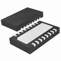
LTC3550EDHC#PBF Linear Technology, LTC3550EDHC#PBF Datasheet - Page 2

LTC3550EDHC#PBF
Manufacturer Part Number
LTC3550EDHC#PBF
Description
IC CHARGER BATT DUAL 16-DFN
Manufacturer
Linear Technology
Datasheet
1.LTC3550EDHCPBF.pdf
(24 pages)
Specifications of LTC3550EDHC#PBF
Function
Charge Management
Battery Type
Lithium-Ion (Li-Ion)
Voltage - Supply
4.3 V ~ 8 V
Operating Temperature
-40°C ~ 85°C
Mounting Type
Surface Mount
Package / Case
16-WFDFN Exposed Pad
Lead Free Status / RoHS Status
Lead free / RoHS Compliant
Available stocks
Company
Part Number
Manufacturer
Quantity
Price
ABSOLUTE AXI U RATI GS
LTC3550
(Note 1)
DCIN, USBIN .............................................. –0.3V to 10V
EN, ⎯ C ⎯ H ⎯ R ⎯ G , ⎯ P ⎯ W ⎯ R , HPWR ............................ –0.3V to 10V
BAT, IDC, IUSB, ITERM ................................ –0.3V to 7V
V
RUN, V
SW (DC) ........................................–0.3V to (V
DCIN Pin Current (Note 2) ..........................................1A
USBIN Pin Current (Note 2) .................................700mA
BAT Pin Current (Note 2) ............................................1A
P-Channel SW Source Current (DC) .....................800mA
N-Channel SW Source Current (DC) ....................800mA
Peak SW Sink and Source Current ...........................1.3A
Operating Temperature Range (Note 3) ... –40°C to 85°C
Maximum Junction Temperature .......................... 125°C
Storage Temperature Range ................... –65°C to 125°C
ELECTRICAL CHARACTERISTICS
temperature range, otherwise specifi cations are at T
2
SYMBOL
V
V
V
V
R
V
I
V
V
V
R
V
V
V
V
RUN
ASD-DC
ASD-USB
DCIN
USBIN
CC
EN
EN
RUN
⎯ C ⎯ H ⎯ R ⎯ G
⎯ P ⎯ W ⎯ R
HPWR
HPWR
UVDC
UVUSB
CC
............................................................... –0.3V to 6V
FB
.....................................................–0.3V to V
PARAMETER
Wall Adapter Input Supply Voltage
USB Port Input Supply Voltage
Buck Regulator Input Supply Voltage
EN Input Threshold Voltage
EN Pull-Down Resistance
RUN Threshold Voltage
RUN Leakage Current
⎯ C ⎯ H ⎯ R ⎯ G Output Low Voltage
⎯ P ⎯ W ⎯ R Output Low Voltage
HPWR Input Threshold Voltage
HPWR Pull-Down Resistance
DCIN Undervoltage Lockout Voltage
USBIN Undervoltage Lockout Voltage
V
V
Voltage
DCIN
USBIN
W
– V
– V
BAT
BAT
Lockout Threshold Voltage V
W W
Lockout Threshold
U
A
CC
= 25°C. V
CONDITIONS
I
I
From Low to High
Hysteresis
From Low to High
Hysteresis
V
V
V
+ 0.3V)
⎯ C ⎯ H ⎯ R ⎯ G
⎯ P ⎯ W ⎯ R
DCIN
DCIN
USBIN
USBIN
The
= 5mA
= 5mA
from Low to High, V
from High to Low, V
CC
from Low to High, V
from High to Low, V
●
DCIN
denotes the specifi cations which apply over the full operating
= 5V, V
PACKAGE/ORDER I FOR ATIO
Consult LTC Marketing for parts specifi ed with wider operating temperature ranges.
Order Options Tape and Reel: Add #TR
Lead Free: Add #PBF Lead Free Tape and Reel: Add #TRPBF
Lead Free Part Marking:
ORDER PART NUMBER
USBIN
LTC3550EDHC
BAT
BAT
BAT
BAT
EXPOSED PAD (PIN 17) IS GND, MUST BE SOLDERED TO PCB
= 5V, V
= 4.2V
= 4.2V
= 4.2V
= 4.2V
ITERM
CC
USBIN
CHRG
16-LEAD (5mm × 3mm) PLASTIC DFN
IUSB
PWR
GND
T
V
V
JMAX
= 3.6V unless otherwise noted.
CC
FB
http://www.linear.com/leadfree/
= 125°C, θ
1
2
3
4
5
6
7
8
●
●
●
●
●
●
DHC PACKAGE
TOP VIEW
17
JA
MIN
140
140
4.3
4.3
2.5
0.4
1.2
0.3
0.4
4.0
3.8
20
20
1
= 40°C (NOTE 4)
U
DHC PART MARKING
16
15
14
13
12
11
10
9
±0.01
0.35
0.35
4.15
3.95
TYP
200
200
180
180
0.7
0.7
50
50
DCIN
BAT
IDC
HPWR
EN
RUN
SW
GND
2
1
2
3550
W
MAX
220
220
5.5
1.0
1.5
0.6
0.6
4.3
4.1
±1
80
80
8
8
5
1
5
UNITS
3550fa
U
MΩ
MΩ
mV
mV
mV
mV
mV
mV
µA
V
V
V
V
V
V
V
V
V
V


