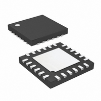
LTC4007EUFD-1#TRPBF Linear Technology, LTC4007EUFD-1#TRPBF Datasheet - Page 19

LTC4007EUFD-1#TRPBF
Manufacturer Part Number
LTC4007EUFD-1#TRPBF
Description
IC CHARGER BATTERY 4A 24-QFN
Manufacturer
Linear Technology
Type
Battery Chargerr
Datasheet
1.LTC4007EUFD-1PBF.pdf
(24 pages)
Specifications of LTC4007EUFD-1#TRPBF
Function
Charge Management
Battery Type
Lithium-Ion (Li-Ion)
Voltage - Supply
6 V ~ 28 V
Operating Temperature
-40°C ~ 85°C
Mounting Type
Surface Mount
Package / Case
24-WFQFN Exposed Pad
Output Current
4A
Output Voltage
4.1/4.2V
Operating Supply Voltage (min)
6V
Operating Supply Voltage (max)
28V
Operating Temp Range
-40C to 85C
Package Type
QFN
Mounting
Surface Mount
Pin Count
24
Operating Temperature Classification
Industrial
Lead Free Status / RoHS Status
Lead free / RoHS Compliant
Available stocks
Company
Part Number
Manufacturer
Quantity
Price
APPLICATIO S I FOR ATIO
If you are using a thermistor that doesn’t have a 1:7 HIGH/
LOW ratio, or you wish to set the HIGH/LOW limits to
different temperatures, then the more generic network in
Figure 10 should work.
Once the thermistor, R
thermistor value is known at the temperature limits, then
resistors R9 and R9A are given by:
For NTC thermistors:
For PTC thermistors:
Example #1: 10kΩ NTC with custom limits
R9 = 6 R
R9A = 6 R
Where R
R9 = 6 R
R9A = 6 R
Where R
TLOW = 0°C, THIGH = 50°C
R
R
R
R9 = 24.55k → 24.3k (nearest 1% value)
R9A = 99.6k → 100k (nearest 1% value)
TH
TH(LOW)
TH(HIGH)
= 10k at 25°C,
Figure 10. General Thermistor Network
TH(LOW)
TH(HIGH)
TH(LOW)
TH(LOW)
TH(LOW)
LTC4007-1
= 32.582k at 0°C
TH(LOW)
= 3.635k at 50°C
NTC
U
> 7 • R
• R
• R
• R
> 7 • R
7
• R
TH(HIGH)
TH(HIGH)
TH(HIGH)
TH(HIGH)
R9
TH
U
, has been selected and the
TH(HIGH)
TH(LOW)
/(R
C7
/(R
/(R
/(R
TH(LOW)
TH(LOW)
TH(HIGH)
TH(HIGH)
W
R9A
– 7 • R
40071
– R
– 7 • R
– R
R
TH
F10
TH(HIGH)
TH(LOW)
U
TH(HIGH)
TH(LOW)
)
)
)
)
Example #2: 100kΩ NTC
Example #3: 22kΩ PTC
Sizing the Thermistor Hold Capacitor
During the hold interval, C7 must hold the voltage across
the thermistor relatively constant to avoid false readings.
A reasonable amount of ripple on NTC during the hold
interval is about 10mV to 15mV. Therefore, the value of C7
is given by:
Example:
TLOW = 5°C, THIGH = 50°C
R
R
R
R9 = 226.9k → 226k (nearest 1% value)
R9A = 1.365M → 1.37M (nearest 1% value)
TLOW = 0°C, THIGH = 50°C
R
R
R
R9 = 43.9k → 44.2k (nearest 1% value)
R9A = 154k
C7 = t
R9 = 24.3k
R
C7 = 0.57µF → 0.56µF (nearest value)
TH
TH(LOW)
TH(HIGH)
TH
TH(LOW)
TH(HIGH)
RT
= 10 • R
= 100k at 25°C,
= 309k (~2 hour timer)
= 22k at 25°C,
HOLD
= 272.05k at 5°C
= 6.53k at 0°C
= 33.195k at 50°C
= 61.4k at 50°C
/(R9/7 • –ln(1 – 8 • 15mV/4.5V))
RT
• 17.5pF/(R9/7 • – ln(1 – 8 • 15mV/4.5V)
LTC4007-1
19
40071f


