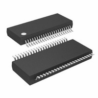
LTC6802IG-1#PBF Linear Technology, LTC6802IG-1#PBF Datasheet - Page 22

LTC6802IG-1#PBF
Manufacturer Part Number
LTC6802IG-1#PBF
Description
IC MONITOR BATT STACK MC 44-SSOP
Manufacturer
Linear Technology
Datasheet
1.LTC6802IG-1PBF.pdf
(38 pages)
Specifications of LTC6802IG-1#PBF
Function
Battery Monitor
Battery Type
Lithium-Ion (Li-Ion)
Voltage - Supply
4 V ~ 50 V
Operating Temperature
-40°C ~ 85°C
Mounting Type
Surface Mount
Package / Case
44-SOP (0.200", 5.30mm Width)
Lead Free Status / RoHS Status
Lead free / RoHS Compliant
Available stocks
Company
Part Number
Manufacturer
Quantity
Price
LTC6802-1
APPLICATIONS INFORMATION
out will be low when any device is busy performing an
A/D conversion and will be high when no device is busy.
Similarly, when polling for interrupt status, the output will
be low when any device has an interrupt condition and will
be high when none has an interrupt condition.
Level polling—Daisy-Chained Broadcast Polling: The SDO
pin (bottom device) or SDI pin (stacked devices) will be
low if a device is busy/in interrupt. If it is not busy/not in
interrupt, the device will pass the level from the SDOI input
to data out (if not the top-of-stack device) or hold the data
out line high (if the top-of-stack device). Therefore, if any
device in the chain is busy or in interrupt, the SDO signal
at the bottom of the stack will be low. If all devices are
not busy/not in interrupt, the SDO signal at the bottom of
the stack will be high.
The master pulls CSBI high to exit polling.
Polling Methods: For A/D conversions, three methods can
be used to determine A/D completion. First, a controller
can start an A/D conversion and wait for the specified
Table 2. Protocol Key
22
Table 3. Broadcast Poll Command
Table 4. Broadcast Read
Table 5. Broadcast Write
Command
Command
Command
PEC
…
N
8
8
8
Packet error code (CRC-8)
Number of bits
Continuation of protocol
Data Byte Low
Data Byte Low
Poll Data
8
8
…
…
Data Byte High
Data Byte High
8
8
conversion time to pass before reading the results. The
second method is to hold CSBI low after an A/D start
command has been sent. The A/D conversion status will be
output on SDO. A problem with the second method is that
the controller is not free to do other serial communication
while waiting for A/D conversions to complete. The third
method overcomes this limitation. The controller can send
an A/D start command, perform other tasks, and then
send a Poll A/D Converter Status (PLADC) command to
determine the status of the A/D conversions.
For OV/UV interrupt status, the Poll Interrupt Status (PLINT)
command can be used to quickly determine whether
any cell in a stack is in an overvoltage or undervoltage
condition.
Bus Protocols
There are 3 different protocol formats, depicted in Table 3
through Table 5. Table 2 is the key for reading the protocol
diagrams.
Shift Byte 1
PEC
8
8
Master-to-slave
Slave-to-master
Complete byte of data
…
Shift Byte 1
8
Shift Byte N
8
…
Shift Byte N
8
68021fa


