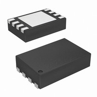
ISL9206DRZ-T Intersil, ISL9206DRZ-T Datasheet - Page 11

ISL9206DRZ-T
Manufacturer Part Number
ISL9206DRZ-T
Description
IC AUTHENTICATION BATTERY 8-TDFN
Manufacturer
Intersil
Series
FlexiHash+™r
Datasheet
1.ISL9206DHZ-T.pdf
(17 pages)
Specifications of ISL9206DRZ-T
Function
Battery Authentication
Battery Type
Li-Ion, Li-Pol, NiMH
Voltage - Supply
2.6 V ~ 4.8 V
Operating Temperature
-20°C ~ 85°C
Mounting Type
Surface Mount
Package / Case
8-TDFN Exposed Pad
Lead Free Status / RoHS Status
Lead free / RoHS Compliant
Available stocks
Company
Part Number
Manufacturer
Quantity
Price
Company:
Part Number:
ISL9206DRZ-T
Manufacturer:
SEMTECH
Quantity:
300
Bus Transaction Protocol
The XSD bus for the ISL9206 defines three types of bus
transactions. Figure 10 shows the bus transaction protocol.
The blue color represents the signal sent by the host and the
green color stands for the signal sent by the device. Before
the transaction starts, the host should make sure that the
XSD device is not in the sleep mode. One method is to
always send a ‘break’ signal before starting the transaction,
as shown in Figure 10. If the device is not in the sleep mode,
the ‘break’ signal is not mandatory. The ‘break’ pulse width
may appear to be wider than what the host sends out
because of the reason explained in Figure 4. The symbols in
Figure 10 are explained in Table 7.
TABLE 7. SYMBOLS IN THE BUS TRANSACTION PROTOCOL
(C) Back-to-Back Transaction (Read Followed by Write).
(B) Multi-Byte Read Instruction.
(A) Multi-Byte Write Instruction.
IFG
IFG
SYM
TA
TA
break
break
break
H
D
H
D
Stage
LSB
1st
Host inter-frame gap
Device inter-frame gap
Host turn-around time
Device turn-around time
T
T
T
SD
SD
SD
FIGURE 10. XSD BUS TRANSACTION PROTOCOL. THE ‘BREAK’ SIGNAL IS OPTIONAL IF THE DEVICE IS AWAKE
DESCRIPTION
Stage
2nd
Read Instruction Frame
FIGURE 11. THE CRC CALCULATOR FOR THE PASSIVE CRC SUPPORT
11
Stage
Read Instruction Frame
Write Instruction Frame
3rd
0 BT
1 BT
MIN
Stage
4th
H
H
1 BT
1 BT
TYP
D
D
800ms
800ms
MAX
ISL9206
Stage
5th
Passive CRC Support
The CRC feature only supports the read transaction in the
ISL9206. When the OPCODE in the instruction is ‘10’, an
8-Bit CRC is automatically calculated for the data bytes
being transferred out. The CRC result is then appended after
the last data byte is read out.
CRC is generated using the DOW CRC polynomial as
follows:
The CRC generation algorithm is logically illustrated in
Figure 11. Prior to a new CRC calculation, the LFSR (linear
feedback shift register) is initialized to zero. The read data to
be transmitted out is concurrently shifted into the CRC
calculator. After the actual data is transmitted out, the final
content of the LFSR is the resulting CRC value. This value is
transmitted out after the read data, with LSB being
transmitted out first.
TA
TA D
IFG H
D
(output from slave)
(output from slave)
Data Frame
Data Frame 1
Stage
Polynom = 1 + X
Data Frame 1
6th
Stage
7th
4
+ X
TA H
IFG D
H
5
IFG
Stage
MSB
D
8th
+ X
H
Next Instruction
(output from slave)
8
Data Frame 2
Data Frame 2
Frame
January 5, 2007
Serial
Data
Output
Serial
FN9260.2


