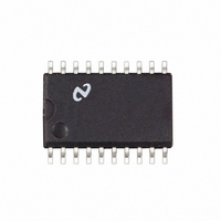
LM3647IM National Semiconductor, LM3647IM Datasheet - Page 8

LM3647IM
Manufacturer Part Number
LM3647IM
Description
IC BATT CHARGER UNIVERSAL 20SOIC
Manufacturer
National Semiconductor
Datasheet
1.LM3647IM.pdf
(14 pages)
Specifications of LM3647IM
Function
Charge Management
Battery Type
Li-Ion, NiCd, NiMH
Voltage - Supply
4.5 V ~ 5.5 V
Operating Temperature
-40°C ~ 85°C
Mounting Type
Surface Mount
Package / Case
20-SOIC (0.300", 7.50mm Width)
Lead Free Status / RoHS Status
Lead free / RoHS Compliant
Other names
*LM3647IM
*LM3647IM/NOPB
LM3647IM/NOPB
*LM3647IM/NOPB
LM3647IM/NOPB
Available stocks
Company
Part Number
Manufacturer
Quantity
Price
Company:
Part Number:
LM3647IM
Manufacturer:
NS
Quantity:
5 510
Part Number:
LM3647IM
Manufacturer:
NS/国半
Quantity:
20 000
Company:
Part Number:
LM3647IM-ND
Manufacturer:
NSC
Quantity:
3
www.national.com
4.0 Functional Description
4.3.3 Charge Current
Charge current selection depends on the type of power
supply used. The LM3647 supports two types: current feed-
back and constant current. The PWM pin is used to control
the power supply and depending on the supply type, it either
produces a simple on/off signal (PWM slow, constant current
supply) or a PWM signal that is filtered externally to a DC
voltage to regulate the charge voltage in a current feedback
power supply (PWM fast). (SEL3 = V
V
4.3.3.1 Current Feedback Power Supply
A current feedback type power supply must be used if charg-
ing Li-Ion batteries. When a current feedback power supply
is used, the charge-current is selected by setting the current
The current-sensing signal is amplified, inverted and cen-
tered on the 2.5V reference by the operational amplifier and
fed into the CS pin on the LM3647. The amplification stage
must be dimensioned by setting the appropriate ratio be-
tween R1 (R2) and R3 (R4). The figure above is dimen-
sioned for a maximum current of about 1.1A. This was
calculated using the following formula:
Example:
With a current feedback power supply the PWM pin must be
configured for “fast” mode (SEL3 = V
V
The RC-network R6, C9 and R5, C1||C2 lowpass-filters the
PWM-signal from the LM3647 to a DC-level that is fed into
the operational amplifier. The resistor R22 is required to
prevent DC-output before the LM3647 has control of the
RC-networks.
CC
CC
R3 = 5.1 kΩ, R1 = 100 kΩ, R5 = 0.047Ω, V
; automatic if SEL2 = open.)
; automatic if SEL2 = open).
→ MaxCurrent ≈ 1.09 Ampere
CC
CC
, if SEL2 = GND or
; if SEL2 = GND or
REF
(Continued)
= 2.5V
8
sensing resistor and the gain of the differential amplification
stage. The current sensing resistor (R5) should be dimen-
sioned such that a voltage drop over it is not too small,
because the signal will be more susceptible to noise and
offsets in the amplification-stage. The resistance should not
be too large either (especially in high-current applications),
because this will only generate more heat from the compo-
nent. A suitable value is one that develops about 50 mV
across the resistor when maximum current flows through it.
4.3.3.2 Constant Current Power Supply
A constant current power supply can only be used with
Ni-Cd/Ni-MH batteries, it can not be used to charge Li-Ion
batteries. With a constant current power supply (NiCd/NiMH
batteries only: SEL2 = GND or V
configured for “slow” mode (SEL3 = GND). In that mode the
PWM-pin turns the external current source on and off at a
rate of 0.1 Hz. (This example is just one of many possible
design solutions.) The PWM-pin (SLOW_PWM) turns the
transistor Q1 on and off. When the transistor is off the
current source is on, and when the transistor is on the
current source is off (V_OUT at approximate 0.7V). The
value of R1 depends on the size of the charge current (see
formula):
10131811
CC
) the PWM pin must be
10131813


