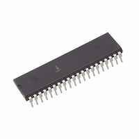
ICL7136CPLZ Intersil, ICL7136CPLZ Datasheet - Page 11

ICL7136CPLZ
Manufacturer Part Number
ICL7136CPLZ
Description
IC ADC 3.5DIGIT LCD LP 40DIP
Manufacturer
Intersil
Datasheet
1.ICL7136CPLZ.pdf
(15 pages)
Specifications of ICL7136CPLZ
Display Type
LCD
Configuration
7 Segment
Digits Or Characters
A/D 3.5 Digits
Current - Supply
70µA
Voltage - Supply
4 V ~ 6 V
Operating Temperature
0°C ~ 70°C
Mounting Type
Through Hole
Package / Case
40-DIP (0.600", 15.24mm)
Package
40PDIP
Resolution
3 1/2 Digit
Sampling Rate
3 SPS
Architecture
Dual Slope
Number Of Analog Inputs
1
Digital Interface Type
LCD
Input Type
Voltage
Polarity Of Input Voltage
Bipolar
Lead Free Status / RoHS Status
Lead free / RoHS Compliant
Interface
-
Available stocks
Company
Part Number
Manufacturer
Quantity
Price
Company:
Part Number:
ICL7136CPLZ
Manufacturer:
INTERSIL
Quantity:
9 756
Part Number:
ICL7136CPLZ
Manufacturer:
INTERSIL
Quantity:
20 000
Reference Voltage
The analog input required to generate full scale output (2000
counts) is: V
V
many applications where the A/D is connected to a
transducer, there will exist a scale factor other than unity
between the input voltage and the digital reading. For
instance, in a weighing system, the designer might like to
have a full scale reading when the voltage from the
transducer is 0.662V. Instead of dividing the input down to
200mV, the designer should use the input voltage directly
and select V
resistor and capacitor would be 330kΩ and 0.047µF. This
makes the system slightly quieter and also avoids a divider
network on the input. Another advantage of this system
occurs when a digital reading of zero is desired for V
Temperature and weighing systems with a variable fare are
examples. This offset reading can be conveniently
generated by connecting the voltage transducer between
IN HI and COMMON and the variable (or fixed) offset
voltage between COMMON and IN LO.
Values shown are for 200mV full scale, 3 readings/sec., floating
supply voltage (9V battery).
REF
FIGURE 8. ICL7136 USING THE INTERNAL REFERENCE
should equal 100mV and 1V, respectively. However, in
COMMON
REF LO
REF HI
lN
REF
OSC 1
OSC 2
OSC 3
IN LO
BUFF
TEST
C
C
IN HI
REF
REF
A-Z
INT
= 2V
BP
V -
G2
C3
A3
G3
= 0.341V. Suitable values for integrating
40
39
38
37
36
35
34
33
32
31
30
29
28
27
26
25
24
23
22
21
REF
0.047µF
. Thus, for the 200mV and 2V scale,
0.47µF
TO DISPLAY
180kΩ
50pF
11
0.1µF
180kΩ
TO BACKPLANE
TO PIN 1
20kΩ
0.01µF
SET V
= 100mV
240kΩ
1MΩ
REF
IN
-
+
+
-
9V
IN
≠ 0.
ICL7136
Typical Applications
The ICL7136 may be used in a wide variety of
configurations. The circuits which follow show some of the
possibilities, and serve to illustrate the exceptional versatility
of these A/D converters.
The following application notes contain very useful
information on understanding and applying this part and are
available from Intersil.
Application Notes
AN016
AN017
AN018
AN023
AN032
AN046
AN052
NOTE #
FIGURE 9. RECOMMENDED COMPONENT VALUES FOR 2V
COMMON
BP/GND
REF LO
“Selecting A/D Converters”
“The Integrating A/D Converter”
“Do’s and Don’ts of Applying A/D Converters”
“Low Cost Digital Panel Meter Designs”
“Understanding the Auto-Zero and Common Mode
Performance of the ICL7136/7/9 Family”
“Building a Battery-Operated Auto Ranging DVM with
the ICL7106”
“Tips for Using Single Chip 3
REF HI
OSC 1
OSC 2
OSC 3
IN LO
BUFF
TEST
C
C
IN HI
FULL SCALE
REF
REF
A-Z
INT
V -
G2
C3
A3
G3
40
39
38
37
36
35
34
33
32
31
30
29
28
27
26
25
24
23
22
21
0.047µF
0.01µF
TO DISPLAY
180kΩ
50pF
DESCRIPTION
0.1µF
1.8M
TO PIN 1
1
250kΩ 240kΩ
/
2
Digit A/D Converters”
0.01µF
SET V
= 100mV
1MΩ
REF
July 21, 2005
+
-
FN3086.6
V+
IN
V-


