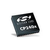
CP2400-GM Silicon Laboratories Inc, CP2400-GM Datasheet - Page 40

CP2400-GM
Manufacturer Part Number
CP2400-GM
Description
IC LCD DRIVER 48QFN
Manufacturer
Silicon Laboratories Inc
Specifications of CP2400-GM
Package / Case
48-QFN
Display Type
LCD
Configuration
128 Segment
Interface
SPI Serial
Current - Supply
620µA
Voltage - Supply
1.8 V ~ 3.6 V
Operating Temperature
-40°C ~ 85°C
Mounting Type
Surface Mount
Data Ram Size
256 B
Interface Type
SPI
Maximum Clock Frequency
25 MHz
Number Of Timers
2
Operating Supply Voltage
1.8 V to 3.6 V
Maximum Operating Temperature
+ 85 C
Mounting Style
SMD/SMT
Minimum Operating Temperature
- 40 C
Lead Free Status / RoHS Status
Lead free / RoHS Compliant
Digits Or Characters
-
Lead Free Status / Rohs Status
Lead free / RoHS Compliant
Other names
336-1855-5
Available stocks
Company
Part Number
Manufacturer
Quantity
Price
Company:
Part Number:
CP2400-GM
Manufacturer:
SIGE
Quantity:
5 000
CP2400/1/2/3
7.
The CP2400/1/2/3 can alert the host processor when any of the interrupt source events listed in Table 7.1 triggers
an interrupt. The CP2400/1/2/3 alerts the host of pending interrupt events by setting the appropriate flags in the
interrupt status registers and driving the INT pin low. The INT pin will remain asserted until all interrupt flags for
enabled interrupts have been cleared by the host. Interrupt flags are cleared by reading the self-clearing interrupt
status registers, INT0 and INT1. Interrupts can be disabled by clearing the corresponding bits in INT0EN and
INT1EN.
Note: When SmaRTClock interrupts are enabled, they are also captured in the ULPST register. If the bits in ULPST are set,
If the host processor does not utilize the INT pin, it can periodically read the interrupt status registers to determine
if any interrupt-generating events have occurred. The INT0RD and INT1RD read-only registers provide a method
of checking for interrupts without clearing the interrupt status registers.
40
SmaRTClock Alarm
SmaRTClock Oscillator Failure
Port Match
Reset Complete
Timer 1 Overflow
Timer 0 Overflow
Interrupt Sources
then the SmaRTClock interrupt flags in the INT0 register will not clear. To clear SmaRTClock interrupt events, first clear
the ULPST register then clear INT0.
Event
Table 7.1. Interrupt Source Events
A SmaRTClock Alarm has occurred.
The SmaRTClock Oscillator has
experienced a failure.
A Port Match event has occurred.
The device is now initialized and ready to
communicate over the host interface.
Timer 1 has overflowed from 0xFFFF to
0x0000 or a SmaRTClock capture event has
occurred.
Timer 0 has overflowed from 0xFFFF to
0x0000.
Rev. 1.0
Description
Pending
INT0.4
INT0.3
INT0.0
INT1.4
INT1.3
INT1.2
Flag
INT0EN.4
INT0EN.3
INT0EN.0
INT1EN.4
INT1EN.3
INT1EN.2
Enable
Flag


