ICL7136CM44Z Intersil, ICL7136CM44Z Datasheet - Page 3
ICL7136CM44Z
Manufacturer Part Number
ICL7136CM44Z
Description
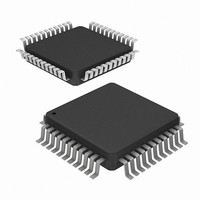
IC ADC 3.5DIGIT LOW PWR 44-MQFP
Manufacturer
Intersil
Datasheet
1.ICL7136CPLZ.pdf
(15 pages)
Specifications of ICL7136CM44Z
Display Type
LCD
Configuration
7 Segment
Digits Or Characters
A/D 3.5 Digits
Current - Supply
70µA
Voltage - Supply
4 V ~ 6 V
Operating Temperature
0°C ~ 70°C
Mounting Type
Surface Mount
Package / Case
44-MQFP, 44-PQFP
Resolution (bits)
3.5bit
Sampling Rate
3SPS
Input Channel Type
Differential
Data Interface
Parallel
Supply Voltage Range - Analogue
9V
Supply Current
70µA
Digital Ic Case Style
MQFP
Rohs Compliant
Yes
Lead Free Status / RoHS Status
Lead free / RoHS Compliant
Interface
-
Available stocks
Company
Part Number
Manufacturer
Quantity
Price
Company:

Part Number:
ICL7136CM44Z
Manufacturer:
Intersil
Quantity:
1 714
Part Number:
ICL7136CM44Z
Manufacturer:
INTERSIL
Quantity:
20 000


Absolute Maximum Ratings
Supply Voltage
Analog Input Voltage (Either Input) (Note 1) . . . . . . . . . . . . V+ to V-
Reference Input Voltage (Either Input). . . . . . . . . . . . . . . . . V+ to V-
Clock Input
Operating Conditions
Temperature Range . . . . . . . . . . . . . . . . . . . . . . . . . . . . 0°C to 70°C
CAUTION: Stresses above those listed in “Absolute Maximum Ratings” may cause permanent damage to the device. This is a stress only rating and operation of the
device at these or any other conditions above those indicated in the operational sections of this specification is not implied.
NOTES:
Electrical Specifications
NOTES:
SYSTEM PERFORMANCE
Zero Input Reading
Ratiometric Reading
Rollover Error
Linearity
Common Mode Rejection Ratio
Noise
Leakage Current Input
Zero Reading Drift
Scale Factor Temperature Coefficient
COMMON Pin Analog Common Voltage
Temperature Coefficient of Analog
Common
SUPPLY CURRENT
V+ Supply Current
DISPLAY DRIVER
Peak-To-Peak Segment Drive Voltage and
Peak-To-Peak Backplane Drive Voltage
1. Input voltages may exceed the supply voltages provided the input current is limited to ±100µA.
2. θ
3. Unless otherwise noted, specifications apply to the ICL7136 at T
4. Back plane drive is in phase with segment drive for “off“ segment, 180 degrees out of phase for “on“ segment. Frequency is 20 times conversion rate.
5. Not tested, guaranteed by design.
6. 48kHz oscillator increases current by 20µA (Typ).
ICL7136, V+ to V-. . . . . . . . . . . . . . . . . . . . . . . . . . . . . . . . . . .15V
ICL7136 . . . . . . . . . . . . . . . . . . . . . . . . . . . . . . . . . . . TEST to V+
Average DC component is less than 50mV.
JA
is measured with the component mounted on a low effective thermal conductivity test board in free air. See Tech Brief TB379 for details.
PARAMETER
3
(Note 3)
V
V
-V
and Negative Inputs Near Full Scale
Full Scale = 200mV or Full Scale = 2V Maximum
Deviation from Best Straight Line Fit (Note 5)
V
V
Exceeded 95% of Time) (Note 5)
V
V
V
25kΩ Between Common and Positive Supply (With Respect
to + Supply)
25kΩ Between Common and Positive Supply (With Respect
to + Supply) (Note 5)
V
Oscillator (Note 6)
V+ to V- = 9V (Note 4)
IN
lN
CM
IN
lN
lN
IN
IN
IN
= V
= 0V (Note 5)
= 0V, 0°C To 70°C (Note 5)
= 0V, Full Scale = 200mV
= 0V, Full Scale = 200mV (Peak-To-Peak Value Not
= 199mV, 0°C To 70°C
= 0 (Does Not Include Common Current) 16kHz
= +V
= ±1V, V
REF
lN
, V
≅ 200mV Difference in Reading for Equal Positive
IN
REF
= 0V, Full Scale = 200mV (Note 5)
= 100mV
A
TEST CONDITIONS
= 25°C, f
ICL7136
,
(Ext. Ref. 0ppm/×°C) (Note 5)
CLOCK
Thermal Information
Thermal Resistance (Typical, Note 2)
Maximum Junction Temperature . . . . . . . . . . . . . . . . . . . . . . . 150°C
Maximum Storage Temperature Range . . . . . . . . . . .-65
Maximum Lead Temperature (Soldering 10s) . . . . . . . . . . . . . 300°C
*Pb-free PDIPs can be used for through hole wave solder
processing only. They are not intended for use in Reflow solder
processing applications.
PDIP Package* . . . . . . . . . . . . . . . . . . . . . . . . . . . .
MQFP Package . . . . . . . . . . . . . . . . . . . . . . . . . . . .
(MQFP - Lead Tips Only)
= 48kHz. ICL7136 is tested in the circuit of Figure 1.
-000.0
MIN
999
2.4
4
-
-
-
-
-
-
-
-
-
±000.0
1000
TYP
999/
±0.2
±0.2
150
0.2
3.0
5.5
50
15
70
1
1
+000.0
MAX
1000
100
3.2
±1
±1
10
1
5
6
-
-
-
o
θ
C to 150°C
July 21, 2005
JA
Reading
Reading
ppm/°C
ppm/°C
Counts
Counts
UNITS
Digital
Digital
µV/°C
µV/V
FN3086.6
(°C/W)
50
75
µV
pA
µA
V
V
Related parts for ICL7136CM44Z
Image
Part Number
Description
Manufacturer
Datasheet
Request
R

Part Number:
Description:
3 1/2 Digit LCD/LED, Low Power Display, A/D Converters with Overrange Recovery
Manufacturer:
Intersil Corporation
Datasheet:
Part Number:
Description:
Intersil Corporation [CMOS Serial Controller Interface]
Manufacturer:
Intersil Corporation
Datasheet:
Part Number:
Description:
Manufacturer:
Intersil Corporation
Datasheet:
Part Number:
Description:
357-036-542-201 CARDEDGE 36POS DL .156 BLK LOPRO
Manufacturer:
Intersil Corporation
Datasheet:
Part Number:
Description:
1024-Word x 4-Bit LSI Static RAM
Manufacturer:
Intersil Corporation
Datasheet:
Part Number:
Description:
General Purpose NPN Transistor Arrays FN341.4
Manufacturer:
Intersil Corporation
Datasheet:
Part Number:
Description:
CMOS 16-Bit Microprocessor
Manufacturer:
Intersil Corporation
Datasheet:
Part Number:
Description:
Manufacturer:
Intersil Corporation
Datasheet:
Part Number:
Description:
Manufacturer:
Intersil Corporation
Datasheet:
Part Number:
Description:
Manufacturer:
Intersil Corporation
Datasheet:
Part Number:
Description:
Manufacturer:
Intersil Corporation
Datasheet:
Part Number:
Description:
CMOS 6-Bit Latch and Decoder Memory Interfaces
Manufacturer:
Intersil Corporation
Datasheet:
Part Number:
Description:
CA3046General Purpose NPN Transistor Arrays
Manufacturer:
Intersil Corporation
Datasheet:
Part Number:
Description:
Manufacturer:
Intersil Corporation
Datasheet:
Part Number:
Description:
TR909 DLC/FLC SLIC with Low Power Standby
Manufacturer:
Intersil Corporation
Datasheet: