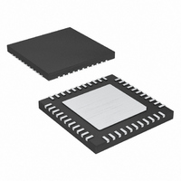
MAX6961ATH+T Maxim Integrated Products, MAX6961ATH+T Datasheet - Page 7

MAX6961ATH+T
Manufacturer Part Number
MAX6961ATH+T
Description
IC DRVR LED 8X8 44-TQFN
Manufacturer
Maxim Integrated Products
Datasheet
1.MAX6963ATH.pdf
(35 pages)
Specifications of MAX6961ATH+T
Display Type
LED
Configuration
8 x 8 (Matrix)
Interface
4-Wire Serial
Digits Or Characters
Any Digit Type
Current - Supply
7.5mA
Voltage - Supply
2.7 V ~ 3.6 V
Operating Temperature
-40°C ~ 125°C
Mounting Type
Surface Mount
Package / Case
44-TQFN Exposed Pad
Number Of Segments
64
Low Level Output Current
750 mA
High Level Output Current
48 mA
Operating Supply Voltage
2.7 V to 3.6 V
Maximum Supply Current
9 mA
Maximum Power Dissipation
2162 mW
Maximum Operating Temperature
+ 125 C
Mounting Style
SMD/SMT
Minimum Operating Temperature
- 40 C
Lead Free Status / RoHS Status
Lead free / RoHS Compliant
• Bicolor: Literally means two color, and usually refers
• Tricolor: Literally means three color, and can refer to
• RGY: Display uses one red LED (R) and one green
• RGB: Display uses one red LED (R), one green LED
The MAX6960 is a multiplexed, constant-current LED
driver intended for high-efficiency indoor signage and
message boards.
The high efficiency arises because the driver operates
from a 3.3V nominal supply with minimal voltage head-
room required across the driver output stages. The
problem of removing heat from even a small display is
therefore minimized.
The maximum peak LED drive current is 40mA, which
when multiplexed eight ways, provides an average cur-
rent of 5mA per LED. This current drive is expected to
be adequate for indoor applications, but inadequate for
outdoor signs operating in direct sun.
The MAX6960 directly drives monocolor (typically red
or orange/yellow) or RGY (typically red/green or
red/yellow) graphic displays using LEDs with a forward
voltage drop up to 2.5V. Blue LEDs and some green
LEDs cannot be driven directly because of their high
forward voltage drop (around 3.5V to 4.5V). For these
displays, the MAX6960 can be used as a graphic con-
troller, just as it can be used for applications requiring
higher peak segment currents, and in RGB panels
needing a higher driver voltage for the blue LEDs. In
these cases, the MAX6960 can be used with external
drive transistors to control anode-row displays, with all
driver features including pixel-level intensity control still
available (see the Applications Information section and
Figure 17).
to LEDs built with two LED dice of different colors,
typically red and green or red and orange/yellow.
LEDs built with three LED dice of different colors, typi-
cally red, green, and blue. The term is also used to
refer to a display built with bicolor LEDs, because there
are three main colors available (red, green, yellow).
LED (G) per pixel. When both red and green LEDs
are lit, the resulting color is yellow (Y). Varying the
current through the LEDs changes the intensity of the
pixel and changes the color from red through shades
of orange and yellow to green.
(G), and one blue LED (B) per pixel. Varying the cur-
rent through the LEDs changes the intensity of the
pixel and changes the color through many shades
limited by the current control resolution.
_______________________________________________________________________________________
MAX6960 Applications
8 x 8 Matrix Graphic LED Drivers
4-Wire Serially Interfaced
Five levels of intensity control are provided:
• A 256-step PWM panel intensity adjustment sets all
• A 2-bits-per-pixel intensity control allows four bright-
• The LED drive current can be selected between
• The LED drive current can be adjusted between
• The digit intensity controls allow each digit’s operat-
The maximum display size that can be handled by a
single 4-wire serial interface is given in Table 2, which
is for the maximum 256 interconnected MAX6960s.
Larger display panels can be designed using a sepa-
rate CS line for each group of (up to) 256 MAX6960s.
Each group would also have its own local 3-wire bus to
allocate the driver addresses. The 4-wire interface
speeds requirement when continuously updating dis-
play memory for high-speed animations is given in
Table 3.
MAX6960s simultaneously as a global panel bright-
ness control (Table 27). The 256-step resolution is
fine enough to allow fade-in/fade-out graphic effects,
as well as provide a means for compensating a
panel for background lighting.
ness levels to be set independently per pixel. The
pixel-level intensity control can be set to be either
arithmetic (off, 1/3, 2/3, full) or geometric (off, 1/4,
1/2, full) for full flexibility (Table 24), and allows four
colors to be displayed on monocolor panels, or 16
colors to be displayed on RGY panels, or 64 colors
to be displayed on RGB panels.
either a 40mA peak per segment and a lower 20mA
peak current on a digit-by-digit basis using the
R
may be the better choice to drive high-efficiency dis-
plays, and this setting allows the MAX6960 to oper-
ate from a supply voltage as low as 2.7V.
40mA and 20mA peak current on a digit-by-digit
basis using fixed or adjustable resistors connected
from the R
trols enable analog relative adjustments in digit
intensity, typically to calibrate digits from different
batches, or to color balance RGY displays.
ing current to be scaled down in 256 steps from the
global panel intensity adjustment. The effective oper-
ating current for each digit becomes n/256th of the
panel intensity value. These controls enable digital
relative adjustments in digit intensity in addition to
the analog approach outlined above.
ISET0
and R
ISET0
ISET1
and R
pins. The lower (20mA) current
Display Intensity Control
Display Size Limitations
ISET1
pins to GND. These con-
7


