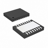
LTC4223CDHD-2#PBF Linear Technology, LTC4223CDHD-2#PBF Datasheet - Page 12

LTC4223CDHD-2#PBF
Manufacturer Part Number
LTC4223CDHD-2#PBF
Description
IC CNTRLR HOT SWAP DUAL 16-DFN
Manufacturer
Linear Technology
Type
Hot-Swap Controllerr
Datasheet
1.LTC4223CDHD-2PBF.pdf
(24 pages)
Specifications of LTC4223CDHD-2#PBF
Applications
ATCA, MicroTCA™
Internal Switch(s)
No
Voltage - Supply
2.7 V ~ 6 V
Operating Temperature
0°C ~ 70°C
Mounting Type
Surface Mount
Package / Case
16-WFDFN Exposed Pad
Lead Free Status / RoHS Status
Lead free / RoHS Compliant
Available stocks
Company
Part Number
Manufacturer
Quantity
Price
LTC4223-1/LTC4223-2
Turn-Off Sequence
The switches can be turned off by various conditions and
this is summarized in Table 1.
When the 12ON pin goes low, the external switch is turned
off with the GATE pin pulled to ground by 1mA current
sink. The ⎯ 1 ⎯ 2 ⎯ P ⎯ G ⎯ O ⎯ O ⎯ D pin pulls high indicating that power is
no longer good, while an internal N-channel transistor dis-
charges the output to ground. Similarly, when the AUXON
pin goes low, the internal switch is turned off, ⎯ A ⎯ U ⎯ X ⎯ P ⎯ G ⎯ O ⎯ O ⎯ D
pulls high while its output is discharged to ground through
an internal N-channel transistor. Figure 3 shows the two
supplies being turned off by ⎯ E ⎯ N going high.
Card Presence Detect
In an AMC system, ⎯ P ⎯ S ⎯ 1 and ⎯ P ⎯ S ⎯ 0 signals are used to
detect the presence of a card upon insertion or removal.
Normally ⎯ P ⎯ S ⎯ 1 is connected to the ⎯ E ⎯ N pin with a pull-up
resistor. If AUXON or 12ON is high when the ⎯ E ⎯ N pin goes
low, indicating a board insertion, a timing cycle for contact
debouncing is initiated. Upon insertion, any bounces on the
⎯ E ⎯ N pin will re-start the timing cycle. When TIMER fi nally
reaches its threshold during ramp up, the fault latches
will be cleared. If the ⎯ E ⎯ N pin remains low at the end of the
timing cycle, the switches are allowed to turn on.
If the ⎯ E ⎯ N pin is toggled from low to high, indicating board
removal, all the switches will be turned off after a 20μs delay.
Any latched faults will not be cleared. However, removing
the card could cause the ⎯ E ⎯ N pin voltage to bounce, clearing
the fault latches undesirably. This is prevented by blanking
12
APPLICATIONS INFORMATION
AUXPGOOD
12PGOOD
Figure 3. Normal Power-Down Sequence
AUXOUT
12V
5V/DIV
5V/DIV
5V/DIV
5V/DIV
5V/DIV
OUT
EN
100ms/DIV
422312 F03
the bounces internally with a TIMER ramp up period given
by C
Timer Functions
An external capacitor C
to ground is used to perform several functions.
1. Ignore contact debouncing during card insertion when
2. Blanking contact bounce on the ⎯ E ⎯ N pin that might
3. Fault fi ltering during auxiliary supply power-up in analog
4. 12V supply fault fi ltering during and after power-up
5. For cooling off during an auto-retry cycle after
the device is enabled. The debounce cycle is given
by ramping up C
threshold (1.235V) and then ramping down with 2μA
current to below TIMER low threshold (0.2V). This gives
an average debounce cycle time of C
After that, if any ON pin is pulled high and ⎯ E ⎯ N pin is
low, the switches can be turned on.
trigger unwanted fault clearing during card removal.
The blanking time is given by C
current limit. TIMER pulls up with 10μA and pulls down
with 2μA. The fi lter time is given by C
in analog current limit. TIMER pulls up with 200μA
and pulls down with 2μA. The fi lter time is given by
C
an overcurrent fault on auxiliary or 12V supply
(LTC4223-2). The cool-off time is given by C
[ms/μF] after an auxiliary supply fault and C
μF] after a 12V supply fault.
T
T
Figure 4. Debouncing by TIMER during Card Removal
• 6[ms/μF].
• 123[ms/μF] as shown in Figure 4.
2V/DIV
1V/DIV
2V/DIV
TIMER
FAULT
EN
T
with 10μA current to TIMER high
T
connected from the TIMER pin
5ms/DIV
T
• 123[ms/μF].
T
T
422312 F04
• 123[ms/μF].
• 741[ms/μF].
T
• 1358[ms/
T
• 1482
422312f


