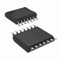
LM5067MW-1/NOPB National Semiconductor, LM5067MW-1/NOPB Datasheet - Page 18

LM5067MW-1/NOPB
Manufacturer Part Number
LM5067MW-1/NOPB
Description
IC CTLR NEG HOTSWAP LATCH 14SOIC
Manufacturer
National Semiconductor
Type
Hot-Swap Controllerr
Datasheet
1.LM5067MM-1NOPB.pdf
(24 pages)
Specifications of LM5067MW-1/NOPB
Applications
General Purpose
Internal Switch(s)
No
Voltage - Supply
-9 V ~ -80 V
Operating Temperature
-40°C ~ 125°C
Mounting Type
Surface Mount
Package / Case
14-SOIC (0.300", 7.50mm Width)
Linear Misc Type
Negative Voltage
Family Name
LM5067-1
Operating Supply Voltage (min)
-9V
Operating Supply Voltage (max)
-80V
Operating Temperature (min)
-40C
Operating Temperature (max)
125C
Operating Temperature Classification
Automotive
Product Height (mm)
2.35mm
Mounting
Surface Mount
Pin Count
14
Lead Free Status / RoHS Status
Lead free / RoHS Compliant
Other names
LM5067MW-1
Available stocks
Company
Part Number
Manufacturer
Quantity
Price
Company:
Part Number:
LM5067MW-1/NOPB
Manufacturer:
TI/NS
Quantity:
2 600
www.national.com
The procedure to calculate the resistor values is as follows:
Q1, and the lower UVLO threshold (V
Q1.
be chosen in advance in this case, but is determined after the
values for R1-R3 are determined. If V
defined in addition to the other three thresholds, see Option
B below.
The resistors are calculated as follows:
The lower OVLO threshold is calculated from:
As an example, assume the application requires the following
thresholds: V
The lower OVLO threshold calculates to -55.8V, and the OV-
LO hysteresis is 4.2V. Note that the OVLO hysteresis is
always slightly greater than the UVLO hysteresis in this con-
figuration.
When the R1-R3 resistor values are known, the threshold
voltages and hysteresis are calculated from the following:
- The lower OVLO threshold (V
- Determine the upper OVLO threshold (V
- Determine the upper UVLO threshold (V
UVH
= -36V, V
UVL
= -32V, V
OVL
), to enable Q1, cannot
UVL
OVL
OVH
) to disable Q1.
must be accurately
= -60V.
OVH
UVH
) to disable
) to enable
18
Note: Ensure the voltages at the UVLO and OVLO pins do
not exceed the Absolute Maximum ratings for those pins
when the system voltage is at maximum.
Option B: If all four thresholds must be accurately defined,
the configuration in Figure 12 can be used.
The four resistor values are calculated as follows:
and the lower UVLO threshold (V
Q1, and the lower OVLO threshold (V
- Determine the upper UVLO threshold (V
- Determine the upper OVLO threshold (V
FIGURE 12. Programming the Four Thresholds
UVL
) to disable Q1.
OVL
) to enable Q1.
UVH
OVH
) to enable Q1,
) to disable
30030951


