DS1862B+ Maxim Integrated Products, DS1862B+ Datasheet
DS1862B+
Specifications of DS1862B+


Related parts for DS1862B+

DS1862B+ Summary of contents
Page 1
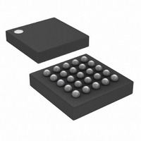
... Operates from 3. Supply ♦ 25-Ball CSBGA, 5mm x 5mm Package Applications ♦ Internal or External Temperature Sensor ♦ -40°C to +100°C Operating Temperature Range ♦ One 8-Bit Buffered DAC PART DS1862B 5 DS1862B+ + Denotes a lead-free/RoHS-compliant package. V CC2 MODSET BIASSET BMD V CC3 Typical Operating Circuit appears at end of data sheet. ...
Page 2
XFP Laser Control and Digital Diagnostic IC ABSOLUTE MAXIMUM RATINGS Voltage Range on Any Open-Drain Pin Relative to Ground.............................................-0.5V to +6.0V Voltage Range on MOD-DESEL, SDA, SCL, FETG, THRSET, TX-D, AUX1MON, AUX2MON, IBIASMON, RSSI, BIASSET, MODSET, EN1, EN2............................................-0. ...
Page 3
XFP Laser Control and Digital Diagnostic IC DC ELECTRICAL CHARACTERISTICS (V = +2.9V to +5.5V +1.6V to +3.6V, T CC3 CC2 PARAMETER SYMBOL Supply Current High-Level Output Voltage (FETG) Low-Level Output Voltage (MOD-NR, INTERRUPT, SDA, FETG) Resistor (Pullup) ...
Page 4
XFP Laser Control and Digital Diagnostic ELECTRICAL CHARACTERISTICS (V = +2.9V to +5.5V -40°C to +100°C, unless otherwise noted.) CC3 A PARAMETER SCL Clock Frequency Clock Pulse-Width Low Clock Pulse-Width High Bus Free ...
Page 5
XFP Laser Control and Digital Diagnostic IC ANALOG OUTPUT CHARACTERISTICS (continued +2.9V to +5.5V +1.6V to +3.6V, T CC3 CC2 PARAMETER SYMBOL I Accuracy MODSET I DNL MODSET I INL MODSET I Temp Drift MODSET I ...
Page 6
XFP Laser Control and Digital Diagnostic IC AC ELECTRICAL CHARACTERISTICS—SOFT* CONTROL AND STATUS (V = +2.9V to +5.5V +1.6V to +3.6V, T CC3 CC2 PARAMETER SYMBOL SOFT TX-D Assert Time t OFF_SOFT SOFT TX-D Deassert Time t ON_SOFT ...
Page 7
XFP Laser Control and Digital Diagnostic IC FAST ALARMS AND V FAULT CHARACTERISTICS +2.9V to +5.5V +1.6V to +3.6V, T CC3 CC2 PARAMETER SYMBOL HIGH BIAS and TX-P Threshold FS V Fault Asserted CC2/3 Falling ...
Page 8
XFP Laser Control and Digital Diagnostic IC V > POA TX-D P-DOWN/RST INTERRUPT I BIASSET t INIT I MODSET Figure 1. Power-On Initialization with P-DOWN/RST Asserted and TX-D/SOFT TX-D Not Asserted V > POA TX-D P-DOWN/RST ...
Page 9
XFP Laser Control and Digital Diagnostic IC TX-F TX-D I BIASSET I MODSET Figure 3. TX-D Timing During Normal Operation OCCURRENCE OF FAULT FETG TX-D I BIASSET I MODSET Figure 4. Detection of Safety Fault Condition Timing Diagrams (continued) t ...
Page 10
XFP Laser Control and Digital Diagnostic IC OCCURRENCE OF FAULT P-DOWN/RST FETG I BIASSET I MODSET Figure 5. Successful Recovery from Transient Safety Fault Condition Using P-DOWN/RST OCCURRENCE OF FAULT P-DOWN/RST FETG (FETG_POL = 1) I BIASSET I MODSET Figure ...
Page 11
XFP Laser Control and Digital Diagnostic IC OCCURRENCE OF MONITOR CHANNEL FAULT INTERRUPT READ FLAGS Figure 7. Monitor Channel Fault Timing Timing Diagrams (continued) t INIT_ON t INIT_OFF ____________________________________________________________________ 11 ...
Page 12
XFP Laser Control and Digital Diagnostic +25°C, unless otherwise noted.) A SUPPLY CURRENT vs. SUPPLY VOLTAGE 6.0 5.5 SRC_SINK_B = 1 5.0 4.5 4.0 3.5 3.0 SRC_SINK_B = 0 2 499.479μA BMD 2.0 2.8 3.3 ...
Page 13
XFP Laser Control and Digital Diagnostic IC NAME PIN Power-Down/Reset Input. This multifunction pin is pulled high internally. See the Power-Down/Reset Pin P-DOWN/RST A1 section for additional information. Signal Conditioner Receiver Loss-of-Signal Input. This pin is an active-high input with ...
Page 14
XFP Laser Control and Digital Diagnostic IC V CC2 V CC3 TEMPERATURE SENSOR IBIASMON AUX2MON MUX RSSI AUX1MON BMD TX-P BMD THRESHOLDS V CC3 V CC3 V CC2 V CC2 ADDRESS R/W DATA BUS V CC3 ...
Page 15
XFP Laser Control and Digital Diagnostic IC Detailed Description The DS1862’s block diagram is described in detail within the following sections and memory map/memory description. Automatic Power Control (APC) The DS1862’s APC is accomplished by closed-loop adjustment of the bias ...
Page 16
XFP Laser Control and Digital Diagnostic IC If the largest current range is selected, the maximum value of FFh (from LUT) corresponds to a 1200μA sink current. Regardless of the current range, the MODSET value always consists of 256 steps, ...
Page 17
XFP Laser Control and Digital Diagnostic IC Monitor Channels The DS1862 has seven monitored voltage signals that are polled in a round-robin multiplexed sequence and are updated with the frame rate, t are read as 16-bit values, but have 13-bit ...
Page 18
XFP Laser Control and Digital Diagnostic IC fault functionality, current on the BIASSET pin is moni- tored by the DS1862 to control the HIGH BIAS quick- trip alarm. Similar to TX-P, the RSSI pin is used to measure the received ...
Page 19
XFP Laser Control and Digital Diagnostic IC Table 8. Temperature Conversion Examples MSB (BIN) LSB (BIN) TEMPERATURE (°C) 01000000 00000000 01000000 00001000 01011111 00000000 11110110 00000000 11011000 00000000 Internal Calibration The DS1862 has two means for scaling an analog input ...
Page 20
XFP Laser Control and Digital Diagnostic IC /* Assume that the Null input is 0.5V addition, the requirement for LSB is 50μ 65536 * 50e-6; /* 3.2768 */ CNT1 = 0.5 / 50e-6; /* ...
Page 21
XFP Laser Control and Digital Diagnostic IC Warning and Alarm Logic Based on AUX1/2MON, V CC2/3 The DS1862 is capable of generating an alarm and/or warning whenever an analog monitored channel goes out of a user-defined tolerance. Temperature, bias cur- ...
Page 22
XFP Laser Control and Digital Diagnostic IC Warning and Alarm Logic Based on Signal Conditioners The DS1862 also has flags that are set by certain logical conditions on signal conditioner (SC) pins: SC-RX-LOL, SC-RX-LOS, SC-TX-LOS. Similarly, for each latched signal ...
Page 23
XFP Laser Control and Digital Diagnostic IC BMD (PIN) ADC (TX-P CURRENT) THRESHOLD BMD (PIN) ADC (TX-P CURRENT) THRESHOLD BIASSET (PIN) ADC (BIASSET CURRENT) THRESHOLD SOFT TX-D P-DOWN/RST (PIN) TX-D (PIN) SAFETY FLAG SOFT P-DOWN/RST Figure 12. Safety Fault and ...
Page 24
XFP Laser Control and Digital Diagnostic IC During an asserted period of P-DOWN/RST (DS1862 in power-down), and V is cycled, the DS1862 remains CC3 in power-down mode upon power-up. While in power- down mode the INTERRUPT pin does not assert. ...
Page 25
XFP Laser Control and Digital Diagnostic SLAVE ADDRESS A0h DEC HEX 0 0 00h LOWER MEMORY DIGITAL DIAGNOSTIC FUNCTIONS PASSWORD ENTRY (PWE) (4 BYTES) TABLE SELECT BYTE 7Fh 127 7F 128 80 80h TABLE 01h TABLE ...
Page 26
XFP Laser Control and Digital Diagnostic IC WORD 0 ADDRESS (hex) BYTE 0/8 BYTE 1/9 <0,2> 00 USER EE Signal Cond* <2> 08 Temp Warn Lo <2> Warn Lo** CC3 <2> 18 Bias Warn Lo <2> 20 TX-P ...
Page 27
XFP Laser Control and Digital Diagnostic IC Bit7 BYTE BYTE/WORD (hex) NAME bit bit 15 14 <1> 57 L-HI-V -W L-LO-V CC5 HI-TEMP-AL <1> 58 MASK HI-RX-P-AL <1> 59 MASK HI-TEMP-W <1> 5A MASK HI-RX-P-W <1> 5B MASK <1> 5C ...
Page 28
XFP Laser Control and Digital Diagnostic IC WORD 0 ADDRESS (hex) Byte 0/8 Byte 1/9 <2> USER EE 80 USER EE <2> USER EE USER EE 88 <2> USER EE USER EE 90 <2> USER EE USER EE 98 <2> ...
Page 29
XFP Laser Control and Digital Diagnostic IC WORD 0 ADDRESS (hex) Byte 0/8 Byte 1/9 BIAS SHIFT, <4> 80 Reserved TX-P SHIFT <4> TX TX-P LO <4> 90 Reserved Reserved MSB RX-P LSB RX-P <4> 98 ...
Page 30
XFP Laser Control and Digital Diagnostic IC WORD 0 ADDRESS (hex) Byte 0/8 Byte 1/9 80–87 DS60 SCALE Bit7 BYTE BYTE/WORD (hex) NAME bit bit 15 14 <5> DS60 SCALE 2 2 <5> LM50 ...
Page 31
XFP Laser Control and Digital Diagnostic IC Bit 0: DATA-NR. Bit is high until DS1862 has achieved power-up. Bit goes low, signaling that monitor channel data is ready to be read. Bit 1: RX-LOS. Indicates optical loss of the signal ...
Page 32
XFP Laser Control and Digital Diagnostic IC DDh • LO MEM 6Eh EN ..............<R-all/W-Module><Shadowed Nonvolatile><00> If bit 5 is high, then bit 3 of 6Eh is not masked. If bit 6 is high, then bit 6 of 6Eh is not ...
Page 33
XFP Laser Control and Digital Diagnostic IC 85h • APC REF FINE .................<R-Module/W-Module><Shadowed Nonvolatile><00> This 2-bit value in <1:0> sets the fine APC current on BMD. The MSB is bit 1. 86h • LUT RANGE .....................<R-Module/W-Module><Shadowed Nonvolatile><00> This 3-bit register ...
Page 34
XFP Laser Control and Digital Diagnostic IC 92h • V SCALE .................<R-Module/W-Module><Shadowed Nonvolatile><Factory Trimmed> This 16-bit CC2/3 register controls the scale value for the V 94h • BIAS SCALE .....................<R-Module/W-Module><Shadowed Nonvolatile><Factory Trimmed> This 16-bit register controls the scale value for ...
Page 35
XFP Laser Control and Digital Diagnostic IC B1h • LUT VALUE ......................<R-Module/W-Module><Shadowed Nonvolatile><00> This register contains the fetched LUT value that drives the MODSET current. It can be read or overwritten to directly control the MODSET current (manual mode). B2h ...
Page 36
XFP Laser Control and Digital Diagnostic IC Security/Password Protection The DS1862 features two separate and independent 32-bit passwords for important memory locations. The host password and the module password allow their own allocated memory locations to be locked to pre- ...
Page 37
XFP Laser Control and Digital Diagnostic IC Bit write: Transitions of SDA must occur during the low state of SCL. The data on SDA must remain valid and unchanged during the entire high pulse of SCL plus the setup and ...
Page 38
XFP Laser Control and Digital Diagnostic IC The memory address is always the second byte trans- mitted during a write operation following the slave address byte Communication Writing a single byte to a slave: The master must ...
Page 39
XFP Laser Control and Digital Diagnostic IC COMMUNICATIONS KEY WHITE BOXES INDICATE THE MASTER IS S START A ACK CONTROLLING SDA NOT SHADED BOXES INDICATE THE SLAVE IS P STOP N ACK CONTROLLING SDA REPEATED ...
Page 40
XFP Laser Control and Digital Diagnostic IC CRC-8 includes and requires the explicit starting mem- ory address to be included as the second transferred byte. Next, the master transfers the data as the DS1862 acknowledges. Only 4 bytes can be ...
Page 41
XFP Laser Control and Digital Diagnostic IC Power-Supply Decoupling To achieve best results recommended that the power supply is decoupled with a 0.01μ 0.1μF capacitor. Use high-quality, ceramic, surface-mount capacitors, and mount the capacitors as close ...
Page 42
XFP Laser Control and Digital Diagnostic IC Chip Information TRANSISTOR COUNT: 75,457 SUBSTRATE CONNECTED TO GROUND 42 ____________________________________________________________________ Package Information For the latest package outline information and land patterns www.maxim-ic.com/packages. PACKAGE TYPE PACKAGE CODE 25 CSBGA X25-1 DOCUMENT ...
Page 43
... Maxim cannot assume responsibility for use of any circuitry other than circuitry entirely embodied in a Maxim product. No circuit patent licenses are implied. Maxim reserves the right to change the circuitry and specifications without notice at any time. Maxim Integrated Products, 120 San Gabriel Drive, Sunnyvale, CA 94086 408-737-7600 ____________________ 43 © 2007 Maxim Integrated Products is a registered trademark of Dallas Semiconductor Corporation ...