DS1862B+ Maxim Integrated Products, DS1862B+ Datasheet - Page 38
DS1862B+
Manufacturer Part Number
DS1862B+
Description
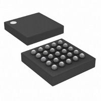
IC LASR CTRLR 7CHAN 5.5V 25CSBGA
Manufacturer
Maxim Integrated Products
Type
Laser Diode Controller (Fiber Optic)r
Datasheet
1.DS1862B.pdf
(43 pages)
Specifications of DS1862B+
Data Rate
10Gbps
Number Of Channels
7
Voltage - Supply
2.9 V ~ 5.5 V
Current - Supply
3mA
Operating Temperature
-40°C ~ 100°C
Package / Case
25-CSBGA
Mounting Type
Surface Mount
Lead Free Status / RoHS Status
Lead free / RoHS Compliant


XFP Laser Control and Digital Diagnostic IC
The memory address is always the second byte trans-
mitted during a write operation following the slave
address byte.
Writing a single byte to a slave: The master must
generate a START condition, write the slave address
byte (R/W = 0), write the memory address, write the
byte of data, and generate a STOP condition.
Remember the master must read the slave’s acknowl-
edgement during all byte write operations.
Writing multiple bytes to a slave: To write multiple
bytes to a slave, the master generates a START condi-
tion, writes the slave address byte (R/W = 0), writes the
memory address, writes up to 4 data bytes, and gener-
ates a STOP condition.
The DS1862 is capable of writing 1 to 4 bytes (referred
to as one row or page) with a single write transaction.
This is internally controlled by an address counter that
allows data to be written to consecutive addresses with-
out transmitting a memory address before each data
byte is sent. The address counter limits the write to one
row of the memory map. Attempts to write to additional
memory rows without sending a STOP condition
between rows results in the address counter wrapping
around to the beginning address of the present row.
To prevent address wrapping from occurring, the mas-
ter must send a STOP condition at the end of the row,
and then wait for the bus free or EEPROM write time to
elapse. Then the master can generate a new START
condition, and write the slave address byte (R/W = 0)
and the first memory address of the next memory row
before continuing to write data.
Acknowledge polling: Any time EEPROM is written,
the DS1862 requires the EEPROM write time (t
the STOP condition to write the contents of the row to
EEPROM. During the EEPROM write time, the DS1862
does not acknowledge its slave address because it is
busy. It is possible to take advantage of this phenome-
non by repeatedly addressing the DS1862, which
allows the next row to be written as soon as the DS1862
is ready to receive the data. The alternative to acknowl-
edge polling is to wait for the maximum period of t
elapse before attempting to write again to the DS1862.
EEPROM write cycles: When EEPROM writes occur,
the DS1862 writes the whole EEPROM memory 4-byte
row even if only a single byte on the row was modified.
38
____________________________________________________________________
I
2
C Communication
W
) after
W
to
Writes that do not modify all 4 bytes on the row are
allowed and do not corrupt the remaining bytes of
memory on the same row. Because the whole row is
written, bytes on the row that were not modified during
the transaction are still subject to a write cycle. This
can result in a whole row being worn out over time by
writing a single byte repeatedly. Writing a row one byte
at a time wears out the EEPROM four times faster than
writing the entire row at once. The DS1862’s EEPROM
write cycles are specified in the Nonvolatile Memory
Characteristics table.
Reading a single byte from a slave: Unlike the write
operation that uses the memory address byte to define
where the data is to be written, the read operation
occurs at the present value of the memory address
counter. To read a single byte from the slave at the
location currently in the address counter, the master
generates a START condition, writes the slave address
byte with R/W = 1, reads the data byte with a NACK to
indicate the end of the transfer, and generates a STOP
condition.
Manipulating the address counter for reads: A
dummy write cycle can be used to force the address
counter to a particular value. To do this the master gen-
erates a START condition, writes the slave address
byte (R/W = 0), writes the memory address where it
desires to read, generates a REPEATED START condi-
tion, writes the slave address byte (R/W = 1), reads
data with ACK or NACK as applicable, and generates a
STOP condition.
See Figure 15 for a read example using the REPEATED
START condition to specify the starting memory location.
Reading multiple bytes from a slave: The read opera-
tion can be used to read multiple bytes with a single
transfer. When reading bytes from the slave, the master
simply ACKs the data byte if it desires to read another
byte before terminating the transaction. After the mas-
ter reads the last byte it NACKs to indicate the end of
the transfer and generates a STOP condition. This can
be done with or without modifying the address
counter’s location before the read cycle. If the address
counter reaches the last physical address, the internal
index pointer loops back to the first memory location in
a given memory table. For example, if address FFh in
Table 02h is read, the next byte of data to be returned
to the master is address 80h in Table 02h, not 00h in
lower memory.
Related parts for DS1862B+
Image
Part Number
Description
Manufacturer
Datasheet
Request
R

Part Number:
Description:
XFP Laser Control and Digital Diagnostic IC
Manufacturer:
Maxim Integrated Products
Part Number:
Description:
MAX7528KCWPMaxim Integrated Products [CMOS Dual 8-Bit Buffered Multiplying DACs]
Manufacturer:
Maxim Integrated Products
Datasheet:
Part Number:
Description:
Single +5V, fully integrated, 1.25Gbps laser diode driver.
Manufacturer:
Maxim Integrated Products
Datasheet:
Part Number:
Description:
Single +5V, fully integrated, 155Mbps laser diode driver.
Manufacturer:
Maxim Integrated Products
Datasheet:
Part Number:
Description:
VRD11/VRD10, K8 Rev F 2/3/4-Phase PWM Controllers with Integrated Dual MOSFET Drivers
Manufacturer:
Maxim Integrated Products
Datasheet:
Part Number:
Description:
Highly Integrated Level 2 SMBus Battery Chargers
Manufacturer:
Maxim Integrated Products
Datasheet:
Part Number:
Description:
Current Monitor and Accumulator with Integrated Sense Resistor; ; Temperature Range: -40°C to +85°C
Manufacturer:
Maxim Integrated Products
Part Number:
Description:
TSSOP 14/A�/RS-485 Transceivers with Integrated 100O/120O Termination Resis
Manufacturer:
Maxim Integrated Products
Part Number:
Description:
TSSOP 14/A�/RS-485 Transceivers with Integrated 100O/120O Termination Resis
Manufacturer:
Maxim Integrated Products
Part Number:
Description:
QFN 16/A�/AC-DC and DC-DC Peak-Current-Mode Converters with Integrated Step
Manufacturer:
Maxim Integrated Products
Part Number:
Description:
TDFN/A/65V, 1A, 600KHZ, SYNCHRONOUS STEP-DOWN REGULATOR WITH INTEGRATED SWI
Manufacturer:
Maxim Integrated Products
Part Number:
Description:
Integrated Temperature Controller f
Manufacturer:
Maxim Integrated Products
Part Number:
Description:
SOT23-6/I�/45MHz to 650MHz, Integrated IF VCOs with Differential Output
Manufacturer:
Maxim Integrated Products
Part Number:
Description:
SOT23-6/I�/45MHz to 650MHz, Integrated IF VCOs with Differential Output
Manufacturer:
Maxim Integrated Products
Part Number:
Description:
EVALUATION KIT/2.4GHZ TO 2.5GHZ 802.11G/B RF TRANSCEIVER WITH INTEGRATED PA
Manufacturer:
Maxim Integrated Products