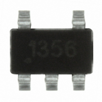
ZXLD1356ET5TA Diodes Zetex, ZXLD1356ET5TA Datasheet - Page 23

ZXLD1356ET5TA
Manufacturer Part Number
ZXLD1356ET5TA
Description
IC LED DRIVR WHITE BCKLGT TSOT-5
Manufacturer
Diodes Zetex
Type
Backlight, White LEDr
Datasheet
1.ZXLD1356ET5TA.pdf
(29 pages)
Specifications of ZXLD1356ET5TA
Topology
PWM, Step-Down (Buck)
Number Of Outputs
1
Internal Driver
Yes
Type - Primary
Automotive, Backlight
Type - Secondary
High Brightness LED (HBLED), White LED
Frequency
500kHz
Voltage - Supply
6 V ~ 60 V
Voltage - Output
60V
Mounting Type
Surface Mount
Package / Case
TSOT-23-5, TSOT-5, TSOP-5
Operating Temperature
-40°C ~ 125°C
Current - Output / Channel
550mA
Internal Switch(s)
Yes
Efficiency
97%
Lead Free Status / RoHS Status
Lead free / RoHS Compliant
Other names
ZXLD1356ET5TR
Available stocks
Company
Part Number
Manufacturer
Quantity
Price
Application Information
Diode selection
For maximum efficiency and performance, the rectifier (D1) should be a fast low capacitance Schottky diode* with low reverse
leakage at the maximum operating voltage and temperature.
They also provide better efficiency than silicon diodes, due to a combination of lower forward voltage and reduced recovery time.
It is important to select parts with a peak current rating above the peak coil current and a continuous current rating higher than
the maximum output load current. It is very important to consider the reverse leakage of the diode when operating above 85°C.
Excess leakage will increase the power dissipation in the device and if close to the load may create a thermal runaway condition.
The higher forward voltage and overshoot due to reverse recovery time in silicon diodes will increase the peak voltage on the LX
output. If a silicon diode is used, care should be taken to ensure that the total voltage appearing on the LX pin including supply
ripple, does not exceed the specified maximum value.
*A suitable Schottky diode would be B1100B (Diodes Inc).
Reducing Output Ripple
Peak to peak ripple current in the LED(s) can be reduced, if required, by shunting a capacitor, Cled, across the LED(s) as shown
below:
A value of 1µF will reduce the supply ripple current by a factor three (approx.). Proportionally lower ripple can be achieved with
higher capacitor values. Note that the capacitor will not affect operating frequency or efficiency, but it will increase start-up delay,
by reducing the rate of rise of LED voltage.
By adding this capacitor the current waveform through the LED(s) changes from a triangular ramp to a more sinusoidal version
without altering the mean current value.
Operation at low supply voltage
Below the under-voltage lockout threshold (V
excessive on-resistance of the output transistor. The output transistor is not full enhanced until the supply voltage exceeds
approximately 17V. At supply voltages between V
on-resistance.
Note that when driving loads of two or more LEDs, the forward drop will normally be sufficient to prevent the device from
switching below approximately 6V. This will minimize the risk of damage to the device.
ZXLD1356
Document number: DS33470 Rev. 3 - 2
(Continued)
V
IN
V
IN
SD
) the drive to the output transistor is turned off to prevent device operation with
Rs
SD
D1
ZXLD1356
and 17V care must be taken to avoid excessive power dissipation due to the
I
SENSE
www.diodes.com
23 of 29
LED
L1
LX
Cled
Diodes Incorporated
A Product Line of
© Diodes Incorporated
ZXLD1356
December 2010


