A6281EESTR-T Allegro Microsystems Inc, A6281EESTR-T Datasheet
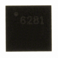
IC LED DRIVER PWM CONTROL 16-QFN

A6281EESTR-T

Manufacturer Part Number
A6281EESTR-T
Description
IC LED DRIVER PWM CONTROL 16-QFN
Manufacturer
Allegro Microsystems Inc
Type
PWM Controlr
Datasheet

Specifications of A6281EESTR-T

Topology
Linear, PWM
Constant Current
Yes
Number Of Outputs
3
Internal Driver
Yes
Type - Secondary
RGB
Frequency
5MHz
Voltage - Supply
4.75 V ~ 17 V
Voltage - Output
1 V ~ 3 V
Mounting Type
Surface Mount
Package / Case
16-WFQFN Exposed Pad
Operating Temperature
-40°C ~ 85°C
Current - Output / Channel
150mA
Internal Switch(s)
Yes
Led Driver Application
Architectural Lighting, Displays
No. Of Outputs
3
Output Current
165mA
Output Voltage
3V
Input Voltage
4.75V To 17V
Operating Supply Voltage (typ)
5/9/12/15V
Number Of Segments
3
Operating Temperature (min)
-40C
Operating Temperature (max)
85C
Operating Temperature Classification
Industrial
Package Type
QFN EP
Pin Count
16
Mounting
Surface Mount
Operating Supply Voltage (min)
4.75V
Operating Supply Voltage (max)
17V
Lead Free Status / RoHS Status
Lead free / RoHS Compliant
Efficiency
-
Lead Free Status / Rohs Status
Compliant
Other names
620-1218-2

Available stocks

Company
Part Number
Manufacturer
Quantity
Price
Part Number:
A6281EESTR-T
Manufacturer:
DIODES
Quantity:
36 500
Part Number:
A6281EESTR-T
Manufacturer:
ALLEGRO/雅丽高
Quantity:
20 000
Features and Benefits
▪ 3 × 10-bit PWM brightness settings
▪ 3 × 7-bit dot correction current settings
▪ 5 to 17 V operation
▪ Wide output current range, 10 to 150 mA per channel
▪ Internally generated PWM clock
▪ Serial port operates at up to 5 MHz
▪ Data and clock logic architecture allows single
▪ Buffered logic outputs to drive cables
▪ Thermal shutdown and UVLO protection
▪ Power-On Reset
Package: 16-terminal QFN (suffix ES)
A6281-DS, Rev. 1
microcontroller control of large quantities of serially-
connected A6281s at fast data transfer rate
Power Supply Bus
Microprocessor
Output Enable
Control Board
Clock
Latch
Data
Figure 1. Functional drawing of daisy chained display application. Additional pixel boards
with A6281 ICs can be applied.
3 mm x 3 mm footprint
Cat5 UTP
Clock In
Data In
Latch In
OE In
3-Channel Constant Current LED Driver
V
V
IN
REG
V
LED
Pixel Board #1
Out
A6281
Application Diagram
R
Out
Clock Out
Latch Out
Data Out
G
OE Out
R
Out
EXT
with Programmable PWM Control
B
Description
The A6281 is a 3-channel constant current LED driver that
has a wide range of output currents. The A6281 controls LED
brightness with a Pulse Width Modulation (PWM) scheme
that gives the application the capability of displaying a billion
colors in an RGB cluster. The maximum current is set by an
external resistor.
The LED brightness is controlled by performing PWM control
on the outputs. The brightness data of the PWM signal for
each LED is stored in three 10-bit registers. The peak value
for each LED can be adjusted (dot-corrected) to compensate
for mismatch, aging, and temperature effects. All the internal
latched registers are loaded by a 32-bit shift register. One
address bit controls whether dot correction/clock divider ratio
or brightness data is loaded into the registers. The remaining
bits are used for the data.
The A6281 is designed to minimize the number of components
needed to drive LEDs with large pixel spacing. A large number
of A6281s can be daisy chained together and controlled by
just four control signals (clock, serial data, latch, and output
enable). Each of these inputs is buffered to drive the next chip
in the chain. Also, VIN can be tied to the LED voltage supply
Continued on the next page…
Cat5 UTP
Clock In
Data In
OE In
Latch In
V
V
IN
REG
V
LED
Pixel Board #2
Out
A6281
R
Out
Clock Out
Latch Out
Data Out
G
OE Out
R
Out
EXT
B
Cat5 UTP
A6281
Pixel Board #N

Related parts for A6281EESTR-T

A6281EESTR-T Summary of contents

Page 1

Features and Benefits ▪ 3 × 10-bit PWM brightness settings ▪ 3 × 7-bit dot correction current settings ▪ operation ▪ Wide output current range 150 mA per channel ▪ Internally generated PWM clock ...

Page 2

... Applications include: ▪ Colored, large-character LED signs ▪ Scrolling, colored marquees Selection Guide Part Number Packing* A6281EESTR-T 1500 pieces/reel *Contact Allegro for additional packing options. Absolute Maximum Ratings Characteristic Load Supply Voltage Output Voltage Output Current ...

Page 3

A6281 SDI CI LI 800 kHz Clock To PWM Counters OEI REXT R VIN EXT Regulator VREG Terminal List Table Number Name 1 REXT An external resistor at this terminal establishes maximum output current 2 VREG Regulator decoupling 3 LGND ...

Page 4

A6281 OPERATING CHARACTERISTICS, valid at T Characteristic ELECTRICAL CHARACTERISTICS Quiescent Supply Current Operating Supply Current Load Supply Voltage Undervoltage Lockout VREG Voltage Range 1 Output Current (any single output) Output to Output Matching Error 2 Output Voltage Range Load Regulation ...

Page 5

A6281 0 CI (External Clock SDI D31 D30 (Serial Data In) SDO (Serial Data Out) LI (Latch In) LO (Latch Out) Internal Oscillator or CI (External Clock) PWM Counter I OUT0 Brightness Data P(OE) ...

Page 6

A6281 Shift Register The A6281 has a 32-bit shift register that loads data through the SDI (serial data in) pin. The shift register operates by a first-in first-out (FIFO) method. The most significant bit (MSB, bit 31) is the first ...

Page 7

A6281 The relationship of the PWM value to the output duty cycle is n given in the following table: PWM Duty Cycle n 0 0/1024 ( 2/1024 2 3/1024 . . . . . . 1023 1024/1024 (100 ...

Page 8

A6281 intended as an external power source. There should be a 1.0 μ ceramic capacitor connected between the V REG pin and LGND. The capacitor should be located as close to the V REG pin as possible. Dot ...

Page 9

A6281 Timing Considerations A6281s can be used in large numbers to drive many LEDs with the control signals connected serially together using short cables between each pixel (see figure 8). Because the clock negative edge drives the data to the ...

Page 10

A6281 8 μF – System Logic Clock Data Latch Output Enable Tie LGND and PGND to PAD externally Figure 8. Application driving 3 RGB LED strings, each maximum + μF – ...

Page 11

A6281 3.00 ±0. 17X 0.08 C +0.05 0.25 –0.07 0.50 +0.15 0.40 –0. 1.70 Copyright ©2006-2008, Allegro MicroSystems, Inc. The products described here are manufactured under one or more U.S. patents or ...

Related keywords