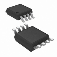
LM3401MM/NOPB National Semiconductor, LM3401MM/NOPB Datasheet - Page 13

LM3401MM/NOPB
Manufacturer Part Number
LM3401MM/NOPB
Description
IC LED DRIVER HIGH BRIGHT 8-MSOP
Manufacturer
National Semiconductor
Series
PowerWise®r
Type
HBLED Driverr
Datasheet
1.LM3401MMNOPB.pdf
(18 pages)
Specifications of LM3401MM/NOPB
Constant Current
Yes
Topology
PWM, Step-Down (Buck)
Number Of Outputs
1
Internal Driver
No
Type - Primary
General Purpose
Type - Secondary
High Brightness LED (HBLED)
Frequency
1.5MHz
Voltage - Supply
4.5 V ~ 35 V
Mounting Type
Surface Mount
Package / Case
8-MSOP, Micro8™, 8-uMAX, 8-uSOP,
Operating Temperature
-40°C ~ 125°C
Current - Output / Channel
1A
Internal Switch(s)
Yes
Efficiency
92%
Operating Supply Voltage (typ)
5/9/12/15/18/24V
Number Of Segments
1
Operating Temperature (min)
-40C
Operating Temperature (max)
125C
Operating Temperature Classification
Automotive
Package Type
MSOP
Pin Count
8
Mounting
Surface Mount
Power Dissipation
660mW
Operating Supply Voltage (min)
4.5V
Operating Supply Voltage (max)
35V
For Use With
LM3401EVAL - BOARD EVALUATION FOR LM3401
Lead Free Status / RoHS Status
Lead free / RoHS Compliant
Voltage - Output
-
Lead Free Status / Rohs Status
Compliant
Other names
LM3401MMTR
Available stocks
Company
Part Number
Manufacturer
Quantity
Price
Part Number:
LM3401MM/NOPB
Manufacturer:
NS/国半
Quantity:
20 000
Design Example
The following design example is intended to illustrate the
step-by-step design process described in the previous sec-
tions. The example refers to the circuit in Figure 11, and the
results are summaized in Table 1. The resulting circuit will
drive a string of 2 Luxeon V Star LEDs at 700 mA from an
input voltage between 18V and 35V.
The example LEDs have a maximum DC current rating of 700
mA, a forward voltage of 5.4V to 8.3V, and a maximum peak
current rating of 1.0A.
First, set the LED DC current with R1:
And the required wattage is:
Select a standard value of 290 mΩ, 1/4W resistor, which will
result in a 690 mA LED DC current.
To keep the peak LED current below I
hysteresis is determined by:
Which gives a maximum R2 value of:
Next, a preferred switching frequency of 1 MHz is selected for
this example.
Since this is a relatively high switching frequency, a low start-
ing point of 25 mV is selected for the comparator hysteresis
to maintain good line regulation. This will allow a larger in-
ductor at the same operating frequency and is well below the
calculated maximum. Set a preliminary hysteresis value with
R2:
SNS
HYS_MAX
W
RSNS
= 700 mA
= (1.0A - .690A) x 0.29Ω = 90 mV
2
x 0.286 = 140 mW
LED_MAX
, the maximum
FIGURE 11. Example Circuit
13
For 1 MHz switching frequency and 25 mV hysteresis, induc-
tance can be calculated. Because frequency varies with input
voltage and LED forward voltage, for this calculation, assume
typical values of 24V and 13.6V respectively, and a PFET
delay time of 15 ns.
Select a value of 33 µH and the hysteresis can be adjusted
downward by re-arranging the same frequency equation:
This gives a new R2 value of 5.6k. This will result in a typical
operating frequency of 1 MHz at 24V
ified that the peak LED current is within the maximum allowed.
For now, the design is created without using a ripple reduction
capacitor. Therefore, LED ripple current is equal to inductor
ripple current. Maximum LED ripple current is calculated as:
Note that the maximum input voltage and minimum anode
voltage were used for this worst case calculation.
Now peak LED current can be determined:
IN
. Next, it must be ver-
30021441
www.national.com


