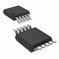
LM3445MM/NOPB National Semiconductor, LM3445MM/NOPB Datasheet - Page 17

LM3445MM/NOPB
Manufacturer Part Number
LM3445MM/NOPB
Description
IC LED DRIVER TRIAC DIMM 10-MSOP
Manufacturer
National Semiconductor
Series
PowerWise®r
Type
Triac Dimmabler
Specifications of LM3445MM/NOPB
Mfg Application Notes
LM3445 Reference Design
Constant Current
Yes
Topology
PWM, Step-Down (Buck)
Number Of Outputs
1
Internal Driver
No
Type - Secondary
High Brightness LED (HBLED)
Frequency
30kHz ~ 1MHz
Voltage - Supply
8 V ~ 12 V
Mounting Type
Surface Mount
Package / Case
10-MSOP, Micro10™, 10-uMAX, 10-uSOP
Operating Temperature
-40°C ~ 125°C
Current - Output / Channel
1A
Internal Switch(s)
Yes
Efficiency
85%
For Use With
LM3445-220VEVAL - BOARD EVAL LM3445 220VLM3445-120VSMEV - BOARD EVAL LM3445 110VLM3445TRIACEVAL - BOARD EVAL LM3445MM
Lead Free Status / RoHS Status
Lead free / RoHS Compliant
Voltage - Output
-
Other names
LM3445MMTR
Available stocks
Company
Part Number
Manufacturer
Quantity
Price
Company:
Part Number:
LM3445MM/NOPB
Manufacturer:
TI
Quantity:
7 000
Design Guide
DETERMINING DUTY-CYCLE (D)
Duty cycle (D) approximately equals:
With efficiency considered:
For simplicity, choose efficiency between 75% and 85%.
CALCULATING OFF-TIME
The “Off-Time” of the LM3445 is set by the user and remains
fairly constant as long as the voltage of the LED stack remains
constant. Calculating the off-time is the first step in determin-
ing the switching frequency of the converter, which is integral
in determining some external component values.
PNP transistor Q3, resistor R4, and the LED string voltage
define a charging current into capacitor C11. A constant cur-
rent into a capacitor creates a linear charging characteristic.
Resistor R4, capacitor C11 and the current through resistor
R4 (i
fixed. Therefore, dv is fixed and linear, and dt (t
be calculated.
Common equations for determining duty cycle and switching
frequency in any buck converter:
Therefore:
COLL
), which is approximately equal to V
LED
OFF
/R4, are all
) can now
17
With efficiency of the buck converter in mind:
Substitute equations and rearrange:
Off-time, and switching frequency can now be calculated us-
ing the equations above.
SETTING THE SWITCHING FREQUENCY
Selecting the switching frequency for nominal operating con-
ditions is based on tradeoffs between efficiency (better at low
frequency) and solution size/cost (smaller at high frequency).
The input voltage to the buck converter (V
both line variations and over the course of each half-cycle of
the input line voltage. The voltage across the LED string will,
however, remain constant, and therefore the off-time remains
constant.
The on-time, and therefore the switching frequency, will vary
as the V
practice is to choose a desired nominal switching frequency
knowing that the switching frequency will decrease as the line
voltage drops and increase as the line voltage increases (see
figure 16).
FIGURE 16. Graphical Illustration of Switching
BUCK
voltage changes with line voltage. A good design
Frequency vs V
BUCK
BUCK
) changes with
www.national.com
30060310


