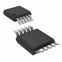
LM3445MM/NOPB National Semiconductor, LM3445MM/NOPB Datasheet - Page 21

LM3445MM/NOPB
Manufacturer Part Number
LM3445MM/NOPB
Description
IC LED DRIVER TRIAC DIMM 10-MSOP
Manufacturer
National Semiconductor
Series
PowerWise®r
Type
Triac Dimmabler
Specifications of LM3445MM/NOPB
Mfg Application Notes
LM3445 Reference Design
Constant Current
Yes
Topology
PWM, Step-Down (Buck)
Number Of Outputs
1
Internal Driver
No
Type - Secondary
High Brightness LED (HBLED)
Frequency
30kHz ~ 1MHz
Voltage - Supply
8 V ~ 12 V
Mounting Type
Surface Mount
Package / Case
10-MSOP, Micro10™, 10-uMAX, 10-uSOP
Operating Temperature
-40°C ~ 125°C
Current - Output / Channel
1A
Internal Switch(s)
Yes
Efficiency
85%
For Use With
LM3445-220VEVAL - BOARD EVAL LM3445 220VLM3445-120VSMEV - BOARD EVAL LM3445 110VLM3445TRIACEVAL - BOARD EVAL LM3445MM
Lead Free Status / RoHS Status
Lead free / RoHS Compliant
Voltage - Output
-
Other names
LM3445MMTR
Available stocks
Company
Part Number
Manufacturer
Quantity
Price
Company:
Part Number:
LM3445MM/NOPB
Manufacturer:
TI
Quantity:
7 000
capacitors are delivering power to the buck converter. When
the triac is firing at 135° the current through the LED string will
be small. Therefore the droop should be small at this point
To determine how many LEDs can be driven, take the mini-
mum voltage the buck converter will see (42.5V) and divide it
by the worst case forward voltage drop of a single LED.
Example: 42.5V/3.7V = 11.5 LEDs (11 LEDs with margin)
OUTPUT CAPACITOR
A capacitor placed in parallel with the LED or array of LEDs
can be used to reduce the LED current ripple while keeping
the same average current through both the inductor and the
LED array. With a buck topology the output inductance (L2)
can now be lowered, making the magnetics smaller and less
expensive. With a well designed converter, you can assume
that all of the ripple will be seen by the capacitor, and not the
LEDs. One must ensure that the capacitor you choose can
handle the RMS current of the inductor. Refer to
manufacture’s datasheets to ensure compliance. Usually an
X5R or X7R capacitor between 1 µF and 10 µF of the proper
voltage rating will be sufficient.
SWITCHING MOSFET
The main switching MOSFET should be chosen with efficien-
cy and robustness in mind. The maximum voltage across the
switching MOSFET will equal:
FIGURE 22. V
FIGURE 21. AC Line with Various Firing Angles
BUCK
Waveforms with Various Firing Angles
21
and a 5% voltage droop should be a sufficient derating. With
this derating, the lowest voltage the buck converter will see is
about 42.5V in this example.
The average current rating should be greater than:
RE-CIRCULATING DIODE
The LM3445 Buck converter requires a re-circulating diode
D10 (see the Typical Application circuit figure 4) to carry the
inductor current during the MOSFET Q2 off-time. The most
efficient choice for D10 is a diode with a low forward drop and
near-zero reverse recovery time that can withstand a reverse
voltage of the maximum voltage seen at V
110V
190V.
The current rating must be at least:
Or:
AC
± 20% line, the reverse voltage could be as high as
I
I
DS-MAX
D
= 1 - (D
= I
LED(-AVE)
MIN
) x I
LED(AVE)
(D
30060356
MAX
BUCK
)
. For a common
www.national.com
30060355


