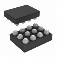
LM3530UME-40/NOPB National Semiconductor, LM3530UME-40/NOPB Datasheet - Page 35

LM3530UME-40/NOPB
Manufacturer Part Number
LM3530UME-40/NOPB
Description
IC LED DRVR PROGRAM I2C 12USMD
Manufacturer
National Semiconductor
Series
PowerWise®r
Datasheet
1.LM3530UME-40NOPB.pdf
(44 pages)
Specifications of LM3530UME-40/NOPB
Topology
PWM, Step-Up (Boost)
Number Of Outputs
1
Internal Driver
Yes
Type - Primary
Backlight
Type - Secondary
White LED
Frequency
500kHz
Voltage - Supply
2.7 V ~ 5.5 V
Mounting Type
Surface Mount
Package / Case
12-UFBGA
Operating Temperature
-40°C ~ 85°C
Current - Output / Channel
Adjustable
Led Driver Application
LED Backlighting, Portable Electronics
No. Of Outputs
1
Output Current
29.5mA
Output Voltage
40V
Input Voltage
2.7V To 5.5V
Rohs Compliant
Yes
Lead Free Status / RoHS Status
Lead free / RoHS Compliant
Voltage - Output
-
Other names
LM3530UME-40TR
Applications Information
LED CURRENT SETTING/MAXIMUM LED CURRENT
The maximum LED current is restricted by the following fac-
tors: the maximum duty cycle that the boost converter can
achieve, the peak current limitations, and the maximum out-
put voltage.
MAXIMUM DUTY CYCLE
The LM3530 can achieve up to typically 94% maximum duty
cycle. Two factors can cause the duty cycle to increase: an
increase in the difference between V
crease in efficiency. This is shown by the following equation:
For a 9-LED configuration V
operating with η = 70% from a 3V battery, the duty cycle re-
quirement would be around 93.6%. Lower efficiency or larger
V
beyond 94%.
PEAK CURRENT LIMIT
The LM3530’s boost converter has a peak current limit for the
internal power switch of 839mA typical (739mA minimum).
When the peak switch current reaches the current limit, the
duty cycle is terminated resulting in a limit on the maximum
output current and thus the maximum output power the
LM3530 can deliver. Calculate the maximum LED current as
a function of V
INDUCTOR SELECTION
The LM3530 is designed to work with a 10µH to 22µH induc-
tor. When selecting the inductor, ensure that the saturation
rating for the inductor is high enough to accommodate the
peak inductor current . The following equation calculates the
peak inductor current based upon LED current, V
Efficiency.
where:
OUT
to V
Manufacturer
Murata
Murata
IN
TDK
differentials can push the duty cycle requirement
IN
, V
OUT
, L, efficiency (η) and I
Part Number
GRM21BR71H105KA12
GRM188B31A225KE33
C1608X5R0J225
OUT
= (3.6V x 9LED + VHR) = 33V
TABLE 12. Recommended Input/Output Capacitors
OUT
and V
PEAK
IN
IN
, V
as:
and a de-
OUT
, and
35
where ƒ
efficiency and I
acteristics.
OUTPUT VOLTAGE LIMITATIONS
The LM3530 has a maximum output voltage of 41V typical
(40V minimum) for the LM3530-40 version and 24V typical
(23.6V minimum) for the 25V version. When the output volt-
age rises above this threshold (V
tection feature is activated and the duty cycle is terminated.
Switching will cease until V
level (typically 1V below V
connected LEDs the output voltage can reach the OVP
threshold at larger LED currents and colder ambient temper-
atures. Typically white LEDs have a -3mV/°C temperature
coefficient.
OUTPUT CAPACITOR SELECTION
The LM3530’s output capacitor has two functions: filtering of
the boost converters switching ripple, and to ensure feedback
loop stability. As a filter, the output capacitor supplies the LED
current during the boost converters on time and absorbs the
inductor's energy during the switch off time. This causes a sag
in the output voltage during the on time and a rise in the output
voltage during the off time. Because of this, the output ca-
pacitor must be sized large enough to filter the inductor cur-
rent ripple that could cause the output voltage ripple to
become excessive. As a feedback loop component, the out-
put capacitor must be at least 1µF and have low ESR other-
wise the LM3530's boost converter can become unstable.
This requires the use of ceramic output capacitors.
lists part numbers and voltage ratings for different output ca-
pacitors that can be used with the LM3530.
When choosing L, the inductance value must also be large
enough so that the peak inductor current is kept below the
LM3530's switch current limit. This forces a lower limit on L
given by the following equation.
I
in the Typical Performance Characteristics, and f
cally 500kHz.
SW_MAX
Value
2.2µF
2.2µF
1µF
SW
is given in the Electrical Table, efficiency (η) is shown
= 500 kHz,and η and I
PEAK
0805
0805
0603
Size
curves in the Typical Performance Char-
OVP
OUT
). For larger numbers of series
Rating
6.3V
50V
10V
drops below the hysteresis
OVP
PEAK
) the over-voltage pro-
can be found in the
Description
COUT
www.national.com
CIN
CIN
SW
Table 12
is typi-


