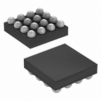
MAX8831EWE+T Maxim Integrated Products, MAX8831EWE+T Datasheet - Page 18

MAX8831EWE+T
Manufacturer Part Number
MAX8831EWE+T
Description
IC LED DRIVR WHITE BCKLGT 16-WLP
Manufacturer
Maxim Integrated Products
Type
Backlight, White LED (I²C Interface)r
Datasheet
1.MAX8831EWET.pdf
(28 pages)
Specifications of MAX8831EWE+T
Topology
Linear (LDO), PWM, Step-Up (Boost)
Number Of Outputs
5
Internal Driver
Yes
Type - Primary
Backlight
Type - Secondary
White LED
Frequency
1.8MHz ~ 2.2MHz
Voltage - Supply
1.6 V ~ 5.5 V
Mounting Type
Surface Mount
Package / Case
16-WLP
Operating Temperature
-40°C ~ 85°C
Internal Switch(s)
Yes
Efficiency
90%
Lead Free Status / RoHS Status
Lead free / RoHS Compliant
Voltage - Output
-
Current - Output / Channel
-
Lead Free Status / Rohs Status
Details
Other names
MAX8831EWE+T
LED_ current regulator. Write a 0 to the LED#_EN bit to
disable that LED_ current regulator. Overvoltage, open
Schottky diode, and thermal-shutdown faults automati-
cally clear all LED#_EN bits to turn off all LED current
regulators.
The LED_ ramp control registers (LED1_RAMP_CNTL
to LED5_RAMP_CNTL) contains the timing information
for each LED current regulator’s ramp-up and ramp-
down rate. The registers at locations 0x03 to 0x07 pro-
gram the ramp rates of the LED1 to LED5 current
regulators, respectively. The ramp-up and ramp-down
rates are programmable with eight different timing
selections. See Table 5.
The LED_ current control registers (ILED1_CNTL to
ILED5_CNTL) program the individual LED1 to LED5
current regulators (see Tables 1 and 2 for programma-
ble values). Registers located at 0x0B and 0x0C pro-
gram the current of the LED1 and LED2 current
regulators (Table 6). Registers located at 0x0D, 0x0E,
and 0x0F program the current of the LED3, LED4, and
LED5 current regulators, respectively (Table 7).
The blink control registers (LED3_BLINK_CNTL to
LED5_BLINK_CNTL) contain the blink control timing
data for the LED3, LED4, and LED5 current regulators.
The registers allow enabling of the blink function and
control the on- and off-time of the blink sequence. The
registers located at 0x17, 0x18, and 0x19 control the
blink timing of the LED3, LED4, and LED5 current regu-
lators, respectively. See Table 8. The LED1 and LED2
current regulators do not have blink functionality.
The boost control register (BOOST_CNTL) determines if
the LED3, LED4, or LED5 current regulators are includ-
ed in the step-up converter regulation loop. If pro-
grammed to be powered from the step-up converter,
LED_ is included in the feedback loop. Otherwise, if
LED_ is programmed to be powered from an alternate
source, LED_ is not included in the feedback loop.
LED3, LED4, and LED5 are high impedance in shut-
down. If the BOOST_CNTL bits are programmed to
power LED3, LED4, or LED5 from an alternate source,
open LED detection is enabled only for that current reg-
ulator. See Table 9. The LED1 and LED2 inputs are
always in the feedback loop and are not programmable
with the boost control register.
High-Efficiency, White LED Step-Up Converter
with I
18
______________________________________________________________________________________
LED3, LED4, and LED5 Blink Control Registers
2
C Interface in 2mm x 2mm WLP
LED_ Current Control Registers
LED_ Ramp Control Registers
Boost Control Register
The LED_ status registers (STAT1, STAT2) indicate the
fault conditions of the MAX8831 IC and LEDs and are
read-only registers. The STAT1 register indicates a fault
condition for each LED_ string, whether a shorted or
open LED_ fault is causing the fault condition. The sec-
ond status register, STAT2, reports the following global
system faults: output overvoltage-condition detection
(OVP), thermal-shutdown condition detection (TSD),
and open Schottky diode detection (OSDD). See
Tables 10 and 11. See the Open/Shorted LED
Detection, Output Overvoltage Protection, Open
Schottky Diode Detection, Thermal-Shutdown
Protection , and System States and Fault Handling sec-
tions for more details.
The CHIP ID registers (CHIP_ID1 and CHIP_ID2) con-
tains MAX8831 die type and mask revision data. These
registers are read-only registers. See Tables 12 and 13.
The MAX8831 is optimized for a 10µH inductor,
although larger or smaller inductors can be used.
Using a smaller inductor results in discontinuous cur-
rent-mode operation over a larger range of output
power, whereas use of a larger inductor results in con-
tinuous conduction for most of the operating range.
To prevent core saturation, ensure that the inductor’s sat-
uration current rating exceeds the peak inductor current
for the application. For larger inductor values and contin-
uous conduction operation, calculate the worst-case
peak inductor current with the following formula:
Otherwise, for small values of L in discontinuous con-
duction operation, I
vides a list of recommended inductors.
Ceramic X5R or X7R dielectric capacitors are recom-
mended for best operation. When selecting ceramic
capacitors in the smallest available case size for a
given value, ensure that the capacitance does not
degrade significantly with DC bias. Generally, ceramic
capacitors with high values and very small case size
have poor DC bias characteristics.
I
PEAK
=
V
OUT
0 9
Applications Information
.
×
×
PEAK
I
V
OUT MAX
IN MIN
(
(
is 860mA (typ). Table 14 pro-
)
)
Capacitor Selection
+
LED_ Status Registers
Inductor Selection
V
IN MIN
(
2
)
×
×
L
0 5
.
μ
s
Chip ID


