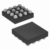
MAX8831EWE+T Maxim Integrated Products, MAX8831EWE+T Datasheet - Page 24

MAX8831EWE+T
Manufacturer Part Number
MAX8831EWE+T
Description
IC LED DRIVR WHITE BCKLGT 16-WLP
Manufacturer
Maxim Integrated Products
Type
Backlight, White LED (I²C Interface)r
Datasheet
1.MAX8831EWET.pdf
(28 pages)
Specifications of MAX8831EWE+T
Topology
Linear (LDO), PWM, Step-Up (Boost)
Number Of Outputs
5
Internal Driver
Yes
Type - Primary
Backlight
Type - Secondary
White LED
Frequency
1.8MHz ~ 2.2MHz
Voltage - Supply
1.6 V ~ 5.5 V
Mounting Type
Surface Mount
Package / Case
16-WLP
Operating Temperature
-40°C ~ 85°C
Internal Switch(s)
Yes
Efficiency
90%
Lead Free Status / RoHS Status
Lead free / RoHS Compliant
Voltage - Output
-
Current - Output / Channel
-
Lead Free Status / Rohs Status
Details
Other names
MAX8831EWE+T
High-Efficiency, White LED Step-Up Converter
with I
Due to fast switching waveforms and high current
paths, careful PCB layout is required. Minimize trace
lengths between the IC and the inductor, the diode, the
input capacitor, and the output capacitor. Minimize
trace lengths between the input and output capacitors
and the MAX8831 GND terminal, and place input and
output capacitor grounds as close together as possi-
ble. Use separate power ground and analog ground
copper areas, and connect them together at the output
capacitor ground. Keep traces short, direct, and wide.
Keep noisy traces, such as the LX node trace, away
from sensitive analog circuitry. For improved thermal
performance, maximize the copper area of the LX and
PGND traces. Refer to the MAX8831 EV Kit for an
example layout.
Table 11. STAT2 Register
(Address 0x2E)
24
B7 (MSB)
B0 (LSB)
BIT
______________________________________________________________________________________
B6
B5
B4
B3
B2
B1
2
NAME
OSDD
TSD
OVP
C Interface in 2mm x 2mm WLP
Reserved for future use
Reserved for future use
Reserved for future use
Reserved for future use
Reserved for future use
Open Schottky diode detection
0 = Schottky diode is present
1 = Schottky diode is missing
Thermal-shutdown detection
0 = No thermal shutdown occurred
1 = MAX8831 has entered thermal
shutdown since the last read
operation of this register
Output overvoltage detection
0 = No overvoltage protection has
occurred
1 = MAX8831 has entered over
voltage protection since last read
operation of this register
DESCRIPTION
PCB Layout
Table 12. CHIP_ID1 Register
(Address: 0x39)
Table 13. CHIP_ID2 Register
(Address 0x3A)
Table 14. Recommended Inductors for
the MAX8831 Circuit
TOKO 1098AS-100M
TOKO 1069AS-220M
FDK MIP3226D100M
Coilcraft EPL2014-
472ML
Coilcraft DO2010-
472ML
B7 (MSB)
B7 (MSB)
B0 (LSB)
B0 (LSB)
BIT
BIT
B6
B5
B4
B3
B2
B1
B6
B5
B4
B3
B2
B1
PART
MASK_REV [3:0]
DIE_TYPE[7:4]
DIE_TYPE[3:0]
DASH [7:4]
(µH)
4.7
4.7
NAME
10
22
10
L
NAME
(mΩ)
DCR
290
570
160
231
800
I
0.75
0.47
650
650
SAT
(A)
0.9
BCD character B
BCD character 0
BCD character 0
BCD character 7
DESCRIPTION
DESCRIPTION
2.0 x 2.0 x 1.45
2.8 x 3.0 x 1.2
3.2 x 2.6 x 1.0
2.0 x 2.0 x 1.0
SIZE (mm)
3 x 3 x 1.8


