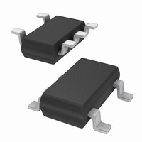
EL7630IWTZ-T7 Intersil, EL7630IWTZ-T7 Datasheet - Page 7

EL7630IWTZ-T7
Manufacturer Part Number
EL7630IWTZ-T7
Description
IC LED DRIVR WHITE BCKLGT TSOT-5
Manufacturer
Intersil
Type
Backlight, White LEDr
Datasheet
1.EL7630ICZ-T7A.pdf
(7 pages)
Specifications of EL7630IWTZ-T7
Topology
PWM, Step-Up (Boost)
Number Of Outputs
1
Internal Driver
Yes
Type - Primary
Backlight
Type - Secondary
White LED
Frequency
1.35MHz
Voltage - Supply
2.7 V ~ 5.5 V
Voltage - Output
27V
Mounting Type
Surface Mount
Package / Case
TSOT-23-5, TSOT-5, TSOP-5
Operating Temperature
-40°C ~ 85°C
Current - Output / Channel
30mA
Internal Switch(s)
Yes
Efficiency
86%
Lead Free Status / RoHS Status
Lead free / RoHS Compliant
Available stocks
Company
Part Number
Manufacturer
Quantity
Price
Company:
Part Number:
EL7630IWTZ-T7
Manufacturer:
TOSHIBA
Quantity:
3 000
Part Number:
EL7630IWTZ-T7
Manufacturer:
INTERSIL
Quantity:
20 000
Part Number:
EL7630IWTZ-T7A
Manufacturer:
INTERSIL
Quantity:
20 000
The efficiency bench test results are shown in Figure 11. In
the test, the input voltage is 4V and 2, 3, 4, 5 and 6 LEDs are
used as the load (boost inductor L = 22µH Sumida
CDRH5D28R-220NC).
White LED Connections
One leg of LEDs connected in series will ensure brightness
uniformity. The 27V maximum output voltage specification
enables up to 6 LEDs to be placed in series.
In order to output more power to drive more LEDs, LEDs
should be in series/parallel connection. Due to the LED's
negative temperature coefficient, in each parallel branch, the
driving source should be high impedance, to balance the
LED current in each branch. One of the ways to ensure the
brightness uniformity is to add mirror current balance circuit,
built up with three transistors for the 15 LEDs series/parallel
connection application shown in Figure 12.
Intersil products are sold by description only. Intersil Corporation reserves the right to make changes in circuit design, software and/or specifications at any time without
notice. Accordingly, the reader is cautioned to verify that data sheets are current before placing orders. Information furnished by Intersil is believed to be accurate and
reliable. However, no responsibility is assumed by Intersil or its subsidiaries for its use; nor for any infringements of patents or other rights of third parties which may result
from its use. No license is granted by implication or otherwise under any patent or patent rights of Intersil or its subsidiaries.
2.7V~5.5V
OFF/ON
FIGURE 11. EFFICIENCY CURVE WITH 2, 3, 4, 5 AND 6 LEDs
FIGURE 12. LEDs IN SERIES/PARALLEL WITH MIRROR
V
IN
C1
90
85
80
75
70
65
60
55
0
LOAD
CURRENT BALANCE
VDD
VDD
ENAB
ENAB
22µH,V
All Intersil U.S. products are manufactured, assembled and tested utilizing ISO9000 quality systems.
EL7630
EL7630
L1
L1
GND
GND
Intersil Corporation’s quality certifications can be viewed at www.intersil.com/design/quality
3LED
IN
LX
LX
FB
FB
=4V
For information regarding Intersil Corporation and its products, see www.intersil.com
6LED
LED CURRENT (mA)
10
4LED
7
R
D1
D1
SET
5LED
2LED
20
LEDs
30
C2
EL7630
PCB Layout Considerations
The PCB layout is very important for the converter to
function properly. For the SC-70 6 pin package, Power
Ground and Signal Ground should be separated to ensure
the high pulse current in the power ground does not interfere
with the sensitive signals connected to Signal Ground. Both
grounds should only be connected at one point right at the
chip. The heavy current loops (V
L1-D1-C2-PGND) should be as short as possible. For the
TSOT 5 pin package, there is no separated GND. All return
GNDs should be connected in GND pin but with no sharing
branch. Based on the signal level on each branch, the lower
power level of the branch, the closer the branch to GND pin
in order to minimize the branch interactive.
The FB pin is most important. The current sense resistor
R
required to the LEDs, a small decoupling capacitor should be
placed at this pin.
The heat of the IC is mainly dissipated through the PGND
pin. Maximizing the copper area connected to this pin is
preferable. In addition, a solid ground plane is always helpful
for the EMI performance.
The demo board is a good example of layout based on the
principle. Please refer to the EL7630 Application Brief for the
layout.
S ET
should be very close to this pin. If a long trace is
IN
-L1-LX-PGND, and V
February 22, 2006
FN7371.1
IN
-


