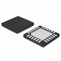
NCP5680MUTXG ON Semiconductor, NCP5680MUTXG Datasheet - Page 17

NCP5680MUTXG
Manufacturer Part Number
NCP5680MUTXG
Description
IC LED DRIVER WHT HI EFF 24-UQFN
Manufacturer
ON Semiconductor
Type
Photo Flash LED (I²C Interface)r
Datasheet
1.NCP5680MUTXG.pdf
(27 pages)
Specifications of NCP5680MUTXG
Topology
Switched Capacitor (Charge Pump)
Number Of Outputs
2
Internal Driver
No
Type - Primary
Flash/Torch
Type - Secondary
White LED
Frequency
850kHz ~ 1.15MHz
Voltage - Supply
2.7 V ~ 5.5 V
Voltage - Output
4.5 V ~ 5.3 V
Mounting Type
Surface Mount
Package / Case
24-UFQFN Exposed Pad, 24-UFQFN
Operating Temperature
-40°C ~ 85°C
Current - Output / Channel
400mA
Internal Switch(s)
Yes
Lead Free Status / RoHS Status
Lead free / RoHS Compliant
Efficiency
-
Lead Free Status / Rohs Status
Details
Available stocks
Company
Part Number
Manufacturer
Quantity
Price
Company:
Part Number:
NCP5680MUTXG
Manufacturer:
ON Semiconductor
Quantity:
2 050
is preset to 50 ms typical and can be set up to a different
timing through an I2C command. Although the NCP5680
can sustain a 255 ms time out, care must be observed, at
system level, that both the external NMOS transistors and
the LED are capable to absorb the increase of temperature
coming from the extra heat developed during a larger time
out sequence.
Typical Sequence:
Select FlashTrigger
CONFIG1[EXTRG)
Set I2CTRIG
Set TimeOut
Send EXTLTRIGGER
Read Flash Pulse
The Flash duration is setup by
the I2C FLWIDx register
The Flash duration is equal to
the EXTL TRIGGER Pulse width
The Flash is switched OFF by
the Time Out control
Select the Photo Sense Mode of Operation
Select the Automatic LED check during a pulse
Select LED2
Select LED1
When the power flash is activated, the default Time out
− send the I2C address
− select the CONFIG0 register
− activate LED1 and LED2
700
650
600
550
500
450
400
350
300
250
200
150
100
50
0
Figure 13. Flash ILED Current vs. Vsense
0.0 0.5 1.0 1.5 2.0 2.5 3.0 3.5 4.0 4.5 5.0 5.5 6.0 6.5
LED Flash Current @ Vbat=3.6V
LED1
FILED(A)
I2C TRIGGER Selected
CONFIG0
$7C
$01
$03
LED2
Figure 12. Flash Mode of Operation
http://onsemi.com
17
− Set up the configuration registers to control the flash
− Set up the pulse width, the amplitude and the delay
Flash Configuration
before a flash takes place:
To generate a flash pulse, several registers must be preset
FILED1
FILED1
FLDLY1
FLDLY2
FLWID1
FLWID2
VOUTREG = $0F ³ set up the output voltage value
TOUT
A typical sequence is depicted here below:
sequence
time
External Trigger Selected
B7
−
−
−
−
B6
−
−
−
−
= $0B ³ LED2 set up the pulse width time
= $0A ³ LED1 set up the pulse width time
= $07 ³ LED1 set up the delay time
= $08 ³ LED2 set up the delay time
= $14 ³ set up the time out
= $03 ³ LED1 set up the peak current
= $04 ³ LED2 set up the peak current
1/0
B5
−
−
−
1/0
B4
−
−
−
B3
I2C TRIGGER Selected
−
−
−
−
B2
−
−
−
−
1/0
B1
−
−
−
1/0
B0
−
−
−


