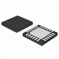
NCP5680MUTXG ON Semiconductor, NCP5680MUTXG Datasheet - Page 23

NCP5680MUTXG
Manufacturer Part Number
NCP5680MUTXG
Description
IC LED DRIVER WHT HI EFF 24-UQFN
Manufacturer
ON Semiconductor
Type
Photo Flash LED (I²C Interface)r
Datasheet
1.NCP5680MUTXG.pdf
(27 pages)
Specifications of NCP5680MUTXG
Topology
Switched Capacitor (Charge Pump)
Number Of Outputs
2
Internal Driver
No
Type - Primary
Flash/Torch
Type - Secondary
White LED
Frequency
850kHz ~ 1.15MHz
Voltage - Supply
2.7 V ~ 5.5 V
Voltage - Output
4.5 V ~ 5.3 V
Mounting Type
Surface Mount
Package / Case
24-UFQFN Exposed Pad, 24-UFQFN
Operating Temperature
-40°C ~ 85°C
Current - Output / Channel
400mA
Internal Switch(s)
Yes
Lead Free Status / RoHS Status
Lead free / RoHS Compliant
Efficiency
-
Lead Free Status / Rohs Status
Details
Available stocks
Company
Part Number
Manufacturer
Quantity
Price
Company:
Part Number:
NCP5680MUTXG
Manufacturer:
ON Semiconductor
Quantity:
2 050
− Byte#1 ³ physical I2C address = %0111 1100 (Write)
/ %0111 1101 (Read)
− Byte#2 ³ select the internal register to read
Example: select the NCP5680 interface ($7C), then select
LED1 output current register, then send the value to be
stored into the LED1 register.
different and five I2C cycles are necessary:
− Byte#1 ³ physical I2C address = %0111 1100 (Write)
to write the STATUS register
− Byte#2 select the STATUS register to read = $17
− Byte#3 ³ send an irrelevant data byte ($FF)
− Force a STOP condition
− Force a START condition
− Byte#4 ³ physical I2C address = %0111 1101 (Read) to
read the STATUS register
− Byte#5³ the NCP5680 returns the STATUS contain on
the SDA line. The MCU must maintain the SCL signal
active.
LED Checking Function
NCP5680 chip, provisions have been made, at silicon level,
to protect the system against fault developed during
operation.
automatic time out sequence engaged when a flash is
activated. Such protection will automatically switch off the
output current if the pulse width exceeds the time out limit
(maximum 255 ms). Similarly, the time out function is
automatically de−activated when the Torch/Video mode of
operation is selected by software. In this case, the
continuous current is limited to 100 mA maximum per LED.
Table 6. I2C Physical address byte (first byte is $7C if Write or $7D is Read)
To read the STATUS register, the protocol is slightly
Although the power transistors are external to the
The first element, in regard to the power flash, is an
SCL
SDA
Read/Write bit = Low −> Write Data
B7
0
Start
B7
NCP5680 address = $7C
= High −> Write Data
NCP5680 returns ACK
ACK = Low −> byte accepted
B6
B6
1
B5
B4
BYTE#1
B3
B2
Figure 22. Typical I2C programming Sequence
B5
B1
1
B0
ACK
Function = $71 −> Set Up LED1 ILED
B7
NCP5680 Function Selection
http://onsemi.com
B4
B6
1
B5
B4
BYTE#2
23
B3
− Byte#3 ³ Data stored into the selected register.
Note: the STATUS register is Read only and no byte can be
stored from the I2C port into this register.
the silicon, the second protection feature is the Vout to
Ground short circuit protection: the output current is
automatically reduced to 60 mA typical, (100 mA max)
when such a short is developed across the output voltage
pin and ground.
to Cathode short might develop in case of failure: such a
situation is detected by the NCP5680 and the associated
current loop is automatically disconnected. The test
procedure shall be launched by forcing the CKPRC bit in
the CONFIG0 register and the procedure is activated upon
the positive going slope of this bit. During the check, a
1 mA / 20 ms width typical bias current is forced through the
LED. To send a new check sequence, the CKPRC bit must
be forced back to low and a new positive edge can be sensed
by forcing CKPRC high.
Ground voltage of each external NMOS to detect any fault
condition in the power flash circuit.
circuit without any on going sequence. The system makes
sure the LED is connected to the Vds pin and that no short
circuit exist between Vout and Vds (no A/K short−circuit).
Such a command over ride the BKL1 and BKL2 status and
the check is carried out even when the BKL1 & BKL2 bits
are low. In case of failure, the chip de−activate the offender
pin and returns the fault bit into the register. The MCU can
read the STATUS register content by means of the I2C
protocol.
B2
Beside the thermal shutdown procedure embedded into
According to the power LED manufacturers, an Anode
Finally, the system permanently monitor the Drain/
A specific command shall be send by the I2C to check the
B3
1
B1
B0
ACK
B7
B2
1
B6
DATA applies to the
ILED = 1000mA
B5
selected register
I2C transmit completed
B4
BYTE#3
B3
B2
B1
0
B1
B0
ACK
R/W
B0


