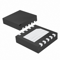
MAX1583ZETB+T Maxim Integrated Products, MAX1583ZETB+T Datasheet - Page 6

MAX1583ZETB+T
Manufacturer Part Number
MAX1583ZETB+T
Description
IC LED DRIVR PHOTO FLASH 10-TDFN
Manufacturer
Maxim Integrated Products
Type
Photo Flash LEDr
Datasheet
1.MAX1583XETBT.pdf
(10 pages)
Specifications of MAX1583ZETB+T
Constant Current
Yes
Topology
Step-Up (Boost)
Number Of Outputs
1
Internal Driver
Yes
Type - Primary
Flash/Torch
Type - Secondary
White LED
Frequency
750kHz ~ 1.25MHz
Voltage - Supply
2.6 V ~ 5.5 V
Voltage - Output
24V
Mounting Type
Surface Mount
Package / Case
10-TDFN Exposed Pad
Operating Temperature
-40°C ~ 85°C
Current - Output / Channel
250mA
Internal Switch(s)
Yes
Efficiency
80%
Number Of Segments
5
Operating Supply Voltage
2.6 V to 5.5 V
Maximum Power Dissipation
1951 mW
Maximum Operating Temperature
+ 85 C
Mounting Style
SMD/SMT
Minimum Operating Temperature
- 40 C
Lead Free Status / RoHS Status
Lead free / RoHS Compliant
White LED Camera-Flash
Boost Converter
6
PIN
10
—
_______________________________________________________________________________________
1
2
3
4
5
6
7
8
9
NAME
MOV
GND
MOV
EN1
EN2
STB
POK
OUT
STB
EN1
EN2
LED
EP
LX
IN
IN
Ground. Connect to exposed paddle.
Input Voltage Supply. Input voltage range is 2.6V to 5.5V. Bypass IN to GND with a 4.7µF ceramic capacitor.
Movie Current-Set Input. Connect a resistor from MOV to GND to set the LED current for movie-mode
operation. R
Strobe Current-Set Input. Connect a resistor from STB to GND to set the LED current for strobe-mode
operation. R
P ow er - O K O utp ut. P ul l ed to GN D d ur i ng p r echar g e m od e. P OK g oes hi g h i m p ed ance once V
Enable 1. EN1 and EN2 are digital inputs that determine the operational mode of the MAX1583. See Table 1.
Enable 2. EN1 and EN2 are digital inputs that determine the operational mode of the MAX1583. See Table 1.
Output-Voltage Sense Input. The boost-converter circuit in the MAX1583 is disabled once V
than 24V. When V
LED Return Input. Connect to the cathode of the series LEDs. Regulates to 0.6V in movie mode. LED is high
impedance during shutdown and precharge mode.
Inductor Connection. Drain of the internal power MOSFET. Connect to the switched side of the inductor. LX is
high impedance during shutdown.
Exposed Paddle. Connect to the circuit ground plane.
DECODE
ENABLE
MAX1583
MOV
STB
CURRENT REGULATOR
REFERENCE
COMPARATOR
MOVIE-MODE
= 600 / I
= 60 / I
FEEDBACK
OUT
GND
falls below 23.5V, the converter is enabled.
LED
LED
(where R
(where R
MOV
STB
THERMAL
> 2kΩ).
> 600kΩ).
LIMIT
BOOST-CONVERTER
CONTROL
FUNCTION
CURRENT-LIMIT
COMPARATOR
COMPARATOR
POK CIRCUITRY
POK
N
Functional Diagram
CURRENT-LIMIT
THRESHOLD
N
Pin Description
N
OU T
OUT
LX
POK
OUT
LED
r eaches 24V .
is greater


