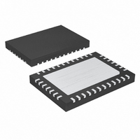
MAX16810ATU+T Maxim Integrated Products, MAX16810ATU+T Datasheet - Page 17

MAX16810ATU+T
Manufacturer Part Number
MAX16810ATU+T
Description
IC LED DRVR WT/RGB BCKLT 38-TQFN
Manufacturer
Maxim Integrated Products
Type
Backlight, White LED, RGB (Serial Interface)r
Specifications of MAX16810ATU+T
Constant Current
Yes
Topology
*
Number Of Outputs
16
Internal Driver
Yes
Type - Primary
Backlight
Type - Secondary
RGB, White LED
Frequency
20kHz ~ 1MHz
Voltage - Supply
8 V ~ 26.5 V
Voltage - Output
36V
Mounting Type
Surface Mount
Package / Case
38-TQFN Exposed Pad
Operating Temperature
-40°C ~ 125°C
Current - Output / Channel
55mA
Internal Switch(s)
No
Low Level Output Current
6 mA
High Level Output Current
1.8 mA
Operating Supply Voltage
3 V to 5.5 V
Maximum Supply Current
5 mA
Maximum Power Dissipation
2857 mW
Maximum Operating Temperature
+ 125 C
Mounting Style
SMD/SMT
Minimum Operating Temperature
- 40 C
Lead Free Status / RoHS Status
Lead free / RoHS Compliant
Efficiency
-
Lead Free Status / Rohs Status
Details
The function of the output capacitor is to reduce the
output ripple to acceptable levels. The ESR, ESL, and
the bulk capacitance of the output capacitor contribute
to the output ripple. In most of the applications, the out-
put ESR and ESL effects can be dramatically reduced
by using low-ESR ceramic capacitors. To reduce the
ESL effects, connect multiple ceramic capacitors in
parallel to achieve the required capacitance.
In a buck configuration, the output capacitance, C
is calculated using the following equation:
where ΔV
In a boost configuration, the output capacitance, C
is calculated as:
where C
Figure 15. SEPIC Configuration
C
C
OUT
OUT
OUT
R
is the maximum allowable output ripple.
is the output capacitor.
≥
V
IN
≥
Δ
C
V
(
TGRM
V
______________________________________________________________________________________
R
C
(
OUT
IN1
V
INMAX
×
with Analog and PWM Dimming Control
Δ
2
V
−
R
×
V
×
L
INMIN
−
V
×
V
OUT
Integrated High-Voltage LED Driver
OUT
R
C
V
TGRM
Output Capacitor
L_REG
INMAX
)
VOUT
×
RT
)
×
×
2
f
SW
×
V
×
OUT
I
OUT
R
R
f
OV1
OV2
SW
2
LV
IN
EN
RT
L_REG
TGRM
DIM
OUT
OUT
R
CS
C
,
,
H_REG
R
MAX16812
REF2
In a buck-boost configuration, the output capacitance,
C
where V
the output current.
An input capacitor connected between IN and ground
must be used when configuring the MAX16812 as a
buck converter. Use a low-ESR input capacitor that can
handle the maximum input RMS ripple current.
Calculate the maximum RMS ripple using the following
equation:
When using the MAX16812 in a boost or buck-boost
configuration, the input capacitor’s RMS current is low
and the input capacitance can be small. However, an
additional electrolytic capacitor may be required to pre-
vent oscillations due to line impedances.
L1
OUT
I
IN(RMS)
R
REF1
is:
C
OUT
OUT
L2
V
IN
R
COMP1
is the voltage across the load and I
=
≥
COMP
I
SRC
DRV
SLP
D
OUT
Δ
GT
OUT
V
R
R
COMP2
C
COMP2
×
×
C
2
(
S
V
R
R
C
SRC
×
V
G
C
OUT
SLP
COMP1
OUT
V
OUT
VOUT
V
+
INMIN
× (
V
×
INMIN
V
Input Capacitor
INMIN
I
OUT
C
)
OUT
×
- V
f
SW
OUT
OUT
)
17
is


