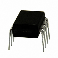
IRS2530DPBF International Rectifier, IRS2530DPBF Datasheet - Page 17

IRS2530DPBF
Manufacturer Part Number
IRS2530DPBF
Description
IC CTRL BALLAST DIMMING 8-DIP
Manufacturer
International Rectifier
Series
DIM8™r
Type
Ballast Controllerr
Datasheet
1.IRS2530DSTRPBF.pdf
(23 pages)
Specifications of IRS2530DPBF
Frequency
34.2 ~ 115 kHz
Current - Supply
5mA
Current - Output
260mA
Voltage - Supply
12.5 V ~ 15.6 V
Operating Temperature
-40°C ~ 125°C
Package / Case
8-DIP (0.300", 7.62mm)
Rohs Compliant
Yes
Peak Reflow Compatible (260 C)
Yes
Supply Current
5mA
Driver Case Style
DIP
No. Of Pins
8
Operating Temperature Range
-40°C To +125°C
Leaded Process Compatible
Yes
For Use With
IRPLDIM5E - KIT DES BALLAST 4LEVEL DIM FLUORIRPLDIM4E - KIT DES BALLAST 26W IRS2530DIRPLCFL8U - KIT DES FLUOR BALLAST IRS2530D
Lead Free Status / RoHS Status
Lead free / RoHS Compliant
Available stocks
Company
Part Number
Manufacturer
Quantity
Price
Company:
Part Number:
IRS2530DPBF
Manufacturer:
IR
Quantity:
3 825
Part Number:
IRS2530DPBF
Manufacturer:
IR
Quantity:
20 000
www.irf.com
Component Selection
Proper design of the circuit schematic (see Typical Application Diagram, Page 1) and component selection is
important for achieving proper ballast functionality and preventing problems. The following design procedure
should be followed for determining the various programming and filtering component values:
1) Capacitor CPH programs the desired preheat/ignition time. CPH is charged up by an internal 1 μA
2) Capacitor CVCO programs the speed of the dimming feedback loop. To ensure smooth and stable
3) Resistor RVCO and capacitor CPH provide additional compensation of the dimming loop to prevent
4) Resistor RCS measures the lamp current for dimming. RCS should be kept small to minimize power
5) The additional feedback components include RFB for current limiting and noise filtering, CFB for DC
6) Capacitors CVCC2 and CBS are the low-side and high-side supply capacitors for maintaining their
current source at the VCO pin. The value of CPH is determined by:
dimming, CVCO should be small enough such that the dimming loop reacts to lamp current changes
each switching cycle. The value of CVCO is typically fixed for most lamp types and is given as:
the VCO voltage from changing too much over a given switching cycle. The value of RVCO is
typically fixed for most lamp types and is given as:
losses but the peak voltage across RCS at the lowest lamp current dimming level should be above a
minimum level to avoid noise problems. Using the minimum rms lamp current during dimming, a
minimum allowable peak voltage level across RCS of 100 mV, and an additional factor of 5 (signal
attenuation due to RFB and CDIM), the value of RCS is determined by:
blocking, and CDIM for noise filtering. The value of these components are typically fixed for most
lamp types and are given as:
respective supply voltages and providing high-frequency noise filtering. These capacitors are
typically fixed and are given as:
Using the maximum rms lamp current, the power loss in resistor RCS is then determined by:
C
P
LOSS
PH
R
=
CS
_
RCS
I
=
VCO
C
V
I
=
VCC
C
VCOFLT
LAMP
C
R
C
⋅
(
VCO
R
VCO
t
DIM
FB
I
PH
2
FB
LAMP
100
_
=
=
/
17
=
=
RMS
IGN
= k
=
C
0
1
2
_
1
10
mV
1 .
BS
5 .
2 .
RMS
_
=
MIN
μ
Ω
k
nF
nF
=
Ω
F
1
_
μ
MAX
0
⋅
A
1 .
⋅
2
μ
4
)
t
V
2
F
PH
×
×
5
/
R
IGN
CS
© 2008 International Rectifier
IRS2530D(S)


